Ford Fusion: Engine - 1.5L EcoBoost (118kW/160PS) – I4 / Engine. Description and Operation
Overview
The 1.5L GTDI 4-cylinder engine has the following features:
- Dual overhead camshafts
- Four valves per cylinder
- Composite intake manifold
- Aluminum cylinder head
- Aluminum cylinder block
- Gasoline turbocharged direct injection (GTDI)
- Twin independent variable cam timing (Ti-VCT)
- Charge air cooler (CAC) (part of intake manifold)
Engine Identification
Always refer to these labels when installation of new parts is necessary or when checking engine calibrations. The engine parts often differ within a CID family. Verification of the identification codes will make sure the correct parts are obtained. These codes contain all the pertinent information relating to the dates, optional equipment and revisions.
Engine Code Information Label
The engine code information label, located on the front side of the timing cover, contains the following:
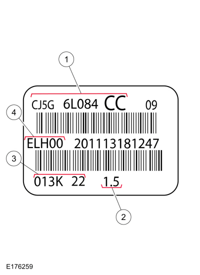
| Item | Description |
|---|---|
| 1 | Engine part number |
| 2 | Engine displacement - 1.5L |
| 3 | Engine build date - 0YYM(A-L)DD |
| 4 | Plant code - Bridgend |
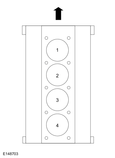
Engine Cylinder Identification
System Operation
Lubrication System
The engine lubrication system is of the force-feed type in which oil is supplied under full pressure to the crankshaft, connecting rod bearings, camshaft bearing caps and variable camshaft timing (VCT) solenoids. The flow of oil to the valve tappets and valve train is controlled by a restricting orifice located in the cylinder head gasket. Conventional oil pumps account for up to 10% of the mechanical power losses at the nominal speed of an engine, leading to increased fuel consumption. This is caused by the high output of the oil pump, especially at high engine speeds. When a variable oil pump is used, the output can be matched to the required oil flow in a flexible manner, depending on the temperature and the engine speed.
The principle component of the variable oil pump is formed by a vane pump with an adjustable outer ring (vane pump adjusting ring). The vane pump adjusting ring is moved to the left or right depending on the oil pressure.
The lubrication system is designed to provide optimum oil flow to critical components of the engine through its entire operating range.
The heart of the system is a positive displacement internal gear oil pump.
Generically, this design is known as a variable oil pump or vane-type pump, which operates as follows:
- The oil pump is driven from the crankshaft.
- At low engine speeds with maximum eccentricity of the vane pump, the maximum volume flow is supplied.
- At high engine speeds, the volume flow increases and with it the oil pressure also. From an oil pressure of approximately 3.25 bar, a valve in the oil pump housing opens (not visible in the illustration), and this causes the oil pressure controlled adjusting ring of the vane pump to be pressed to the left.
- Because of the movement of the adjusting ring, the eccentricity decreases and consequently the delivery volume of the vane pump is reduced. Because of the reduction in the delivery volume, matching to the actual requirement of the internal combustion engine is achieved.
- Advantage: The output can be flexibly matched to the required oil volume flow. Because of this, the power drain at the oil pump is lower, ultimately leading to a reduction in fuel consumption and exhaust emissions.
Valve Train
The valve train uses direct acting mechanical buckets (DAMB). The camshaft lobes are positioned directly above mechanical buckets which are positioned on top of the valves.
Twin Independent Variable Cam Timing (Ti-VCT)
The Ti-VCT system allows variable control of the valves which optimizes combustion at full load providing improved power and low speed torque (broadening the torque curve) which enables variable valve overlap which provides better fuel economy and emissions and provides optimized cold start operation with improved exhaust emissions.
 Specifications
Engine
Item
Specification
Displacement
1.5L Gasoline Turbocharged Direct Injection (GTDI)
No...
 Engine Component View. Description and Operation
Upper Engine
Item
Part Number
Description
1
67506750
Oil level indicator
2
12A36612A366
Ignition coil on plug (4 required)
3
9D3769D376
Fuel injection pump
4
9D3549D354
Fuel injection pump-to-fuel rail fuel supply tube
5
9H4879H487
Fuel rail
6
6C2876C287
Fuel injection pump tappet
7
9F5939F593
Fuel injector (4..
Other information:
Ford Fusion 2013–2020 Service Manual: Selector Lever Cable Bushing. Removal and Installation
Removal Turn the ignition switch to the OFF position and apply the parking brake. Remove the air cleaner assembly. Refer to: Air Cleaner (303-12D Intake Air Distribution and Filtering - 2.7L EcoBoost (238kW/324PS), Removal and Installation). Refer to: Air Cleaner (303-12C Intake Air Distribution and Filtering - 2.5L Duratec (125kW/170PS), Removal and Instal..
Ford Fusion 2013–2020 Service Manual: SYNC Module [APIM] - Police. Removal and Installation
Special Tool(s) / General Equipment Interior Trim Remover Removal NOTE: Removal steps in this procedure may contain installation details. Remove the retainer, release the clips and remove the RH center instrument panel trim panel. Use the General Equipment: Interior Trim Remover Remove the retainers and the APIM. Disconnect the el..
Categories
- Manuals Home
- 2nd Generation Ford Fusion Owners Manual
- 2nd Generation Ford Fusion Service Manual
- Starter Motor. Removal and Installation
- Transmission - 1.5L EcoBoost (118kW/160PS) – I4. Removal and Installation
- Under Hood Overview - 1.5L EcoBoost™, 2.0L EcoBoost™, 2.5L, 2.7L EcoBoost™
- New on site
- Most important about car
Using Seatbelts During Pregnancy
WARNING: Always ride and drive with your seatback upright and properly fasten your seatbelt. Fit the lap portion of the seatbelt snugly and low across the hips. Position the shoulder portion of the seatbelt across your chest. Pregnant women must follow this practice. See the following figure.
