Ford Fusion: Automatic Transmission - 6-Speed Automatic Transmission – 6F35 / Differential. Description and Operation
Differential Exploded View
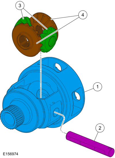
| Item | Description |
| 1 | Differential housing |
| 2 | Pinion shaft |
| 3 | Pinion gears |
| 4 | Side gears |
Differential Cutaway View and External Sealing
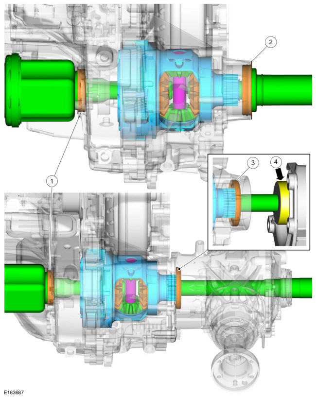
| Item | Description |
| 1 | LH halfshaft seal |
| 2 | RH halfshaft seal FWD (front wheel drive) |
| 3 | RH halfshaft seal AWD (All-wheel drive) |
| 4 | Power Transfer Unit (PTU) input shaft sealing surface |
Differential
The differential allows the halfshafts and wheels to rotate at different speeds during cornering and transfers power to the Power Transfer Unit (PTU) for AWD vehicles.
The differential assembly consists of the following components:
- Differential case (part of the final drive carrier)
- Two pinion gears supported by a pinion shaft
- Two side gears supported by the differential case and halfshafts
When driving in a straight line, both front wheels rotate at relatively the same speed. This means both side gears are rotating at the same speed, as well, while both pinion gears revolve (but do not rotate) with the side gears. During cornering, the wheel on the outside of the turn is forced to rotate faster than the wheel on the inside of the turn. Since the side gears must now rotate at different speeds, the pinion gears rotate on the pinion shaft allowing the drive axles to rotate at different speeds while still transferring output torque.

 Transmission Fluid Auxiliary Pump. Description and Operation
Transmission Fluid Auxiliary Pump Components
Item
Description
1
Transmission assembly
2
Transmission fluid auxiliary pump supply tube assembly
3
Check ball (part of the transmission fluid auxiliary pump supply tube)
4
Transmission fluid auxiliary pump-to-transmission case gasket
5
Tran..
Other information:
Ford Fusion 2013–2020 Service Manual: Blower Motor Speed Control. Removal and Installation
Removal NOTE: Remove steps in this procedure may contain installation details. WARNING: Before beginning any service procedure in this section, refer to Safety Warnings in section 100-00 General Information. Failure to follow this instruction may result in serious personal injury. Refer to: Climate Control System Health and Safety Precautions (100-00 General Informati..
Ford Fusion 2013–2020 Owners Manual: Global Opening and Closing
You can use the remote control to operate the windows with the ignition off. Note: You can enable or disable this feature in the information display or see an authorized dealer. Note: To operate this feature, accessory delay must not be active. Opening the Windows You can only open the windows for a short time after you unlock your vehicle with the remote control. After you unlock your vehi..
Categories
- Manuals Home
- 2nd Generation Ford Fusion Owners Manual
- 2nd Generation Ford Fusion Service Manual
- Front Controls Interface Module (FCIM). Removal and Installation
- Starter Motor. Removal and Installation
- Memory Function
- New on site
- Most important about car
Cross Traffic Alert System Sensors
The sensors are behind the rear bumper on both sides of your vehicle.