Ford Fusion: Electronic Engine Controls - 1.5L EcoBoost (118kW/160PS) – I4 / Cylinder Head Temperature (CHT) Sensor. Removal and Installation
Ford Fusion 2013–2020 Service Manual / Powertrain / Engine / Electronic Engine Controls - 1.5L EcoBoost (118kW/160PS) – I4 / Cylinder Head Temperature (CHT) Sensor. Removal and Installation
Removal
NOTE: Removal steps in this procedure may contain installation details.
-
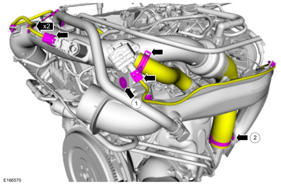
Remove the air cleaner outlet pipe.
Refer to: Air Cleaner Outlet Pipe (303-12A Intake Air Distribution and Filtering - 1.5L EcoBoost (118kW/160PS) – I4, Removal and Installation).
-
-
Disconnect the turbo bypass valve and boost pressure
sensor electrical connector. Remove the mounting screw and release the
wiring retainers.
Torque: 71 lb.in (8 Nm)
-
Disconnect the turbo bypass valve hose and the turbocharger outlet pipe clamp.
Torque: 44 lb.in (5 Nm)
-
Disconnect the turbo bypass valve and boost pressure
sensor electrical connector. Remove the mounting screw and release the
wiring retainers.
 |
-
-
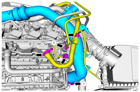
Loosen the turbocharger outlet clamp and disconnect the IAT2 and crankcase pressure sensors.
Torque: 44 lb.in (5 Nm)
-
Release the quick release couplers and remove the turbocharger outlet pipe.
Refer to: Quick Release Coupling (310-00A Fuel System - General Information - 1.5L EcoBoost (118kW/160PS) – I4, General Procedures).
-
Loosen the turbocharger outlet clamp and disconnect the IAT2 and crankcase pressure sensors.
 |
-
-
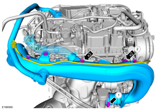
Disconnect the turbochager inlet pipe clamp.
Torque: 44 lb.in (5 Nm)
-
Remove the mounting retainers and release the wiring harness retainers, remove the turbocharger inlet pipe.
Torque: 71 lb.in (8 Nm)
-
Disconnect the turbochager inlet pipe clamp.
 |
-
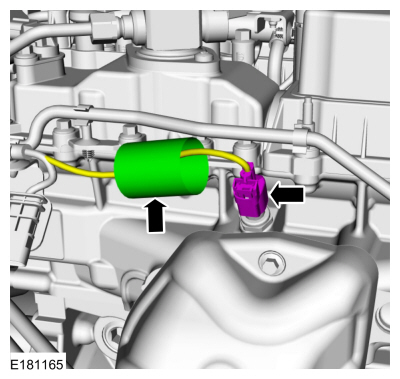
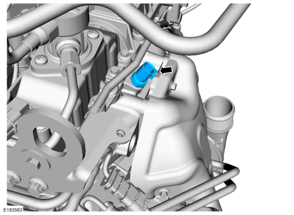
Slide the connector cover and disconnect the CHT sensor electrical connector.
 |
-
Remove the CHT sensor.
Torque: 89 lb.in (10 Nm)
 |
Installation
-
To install, reverse the removal procedure.
 Crankshaft Position (CKP) Sensor. Removal and Installation
Removal
NOTE:
Removal steps in this procedure may contain installation details.
With the vehicle in N, position it on a hoist.
Refer to: Jacking and Lifting - Overview (100-02 Jacking and Lifting, Description and Operation)...
 Engine Coolant Temperature (ECT) Sensor. Removal and Installation
Materials
Name
Specification
Motorcraft® Orange Prediluted Antifreeze/CoolantVC-3DIL-B
WSS-M97B44-D2
Removal
NOTE:
Removal steps in this procedure may contain installation details...
Other information:
Ford Fusion 2013–2020 Service Manual: Steering Wheel and Column Electrical Components - Overview. Description and Operation
Steering Column Switches Overview The steering column switches are located on and around the steering column. This enables the driver to control various vehicle functions and remain focused on driving. Depending on vehicle options, the steering column switches consist of: Multifunction switch - mounted on the left side of the SCCM and can be serviced separately...
Ford Fusion 2013–2020 Service Manual: High Mounted Stoplamp. Removal and Installation
Removal NOTE: Removal steps in this procedure may contain installation details. Partially lower the headliner. Remove the high mounted stoplamp. Disconnect the high mounted stoplamp electrical connector. Remove the nuts...
Categories
- Manuals Home
- 2nd Generation Ford Fusion Owners Manual
- 2nd Generation Ford Fusion Service Manual
- Under Hood Overview - 1.5L EcoBoost™, 2.0L EcoBoost™, 2.5L, 2.7L EcoBoost™
- Front Controls Interface Module (FCIM). Removal and Installation
- Transmission - 1.5L EcoBoost (118kW/160PS) – I4. Removal and Installation
- New on site
- Most important about car
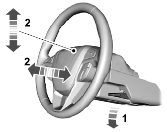
Adjusting the Steering Wheel
WARNING: Do not adjust the steering wheel when your vehicle is moving.
Note: Make sure that you are sitting in the correct position.
Copyright © 2026 www.fofusion2.com