Ford Fusion: Engine Cooling - 1.5L EcoBoost (118kW/160PS) – I4 / Cooling Fan Motor and Shroud. Removal and Installation
Special Tool(s) /
General Equipment
| Hose Clamp Remover/Installer |
Removal
NOTE:
Removal steps in this procedure may contain installation details.
-
Refer to: Engine Cooling System Health and Safety Precautions (100-00 General Information, Description and Operation).
-
Drain the cooling system.
Refer to: Engine Cooling System Draining, Vacuum Filling and Bleeding (303-03A Engine Cooling - 1.5L EcoBoost (118kW/160PS) – I4, General Procedures).
-
Remove the air cleaner.
Refer to: Air Cleaner (303-12A Intake Air Distribution and Filtering - 1.5L EcoBoost (118kW/160PS) – I4, Removal and Installation).
-
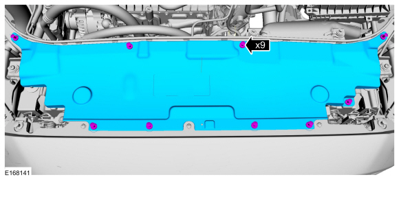
Remove the pin-type retainers and the sight shield.
-
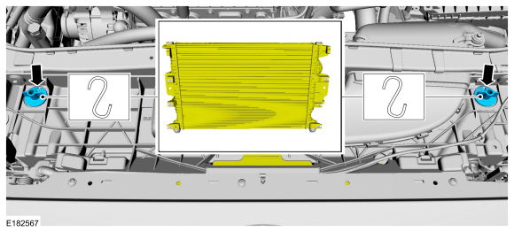
Support each side of the cooling module. The cooling
module must be allowed to drop 1-2 inches to allow clearance for cooling
fan removal.
-
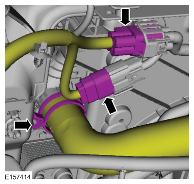
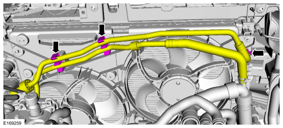
Disconnect the electrical connectors, release the clamp and disconnect the upper radiator hose.
Use the General Equipment: Hose Clamp Remover/Installer
-
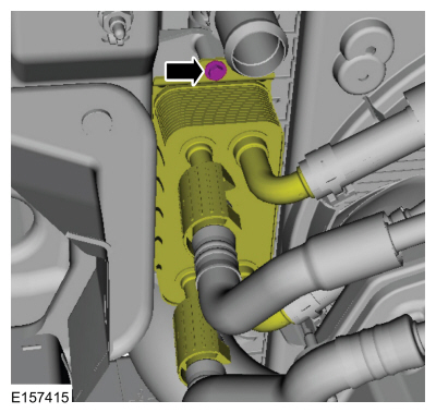
Remove the bolt and position the transmission fluid cooler aside.
Torque:
44 lb.in (5 Nm)
-
Release the clamp and disconnect the coolant hose. Detach the coolant hoses from the retainers.
-
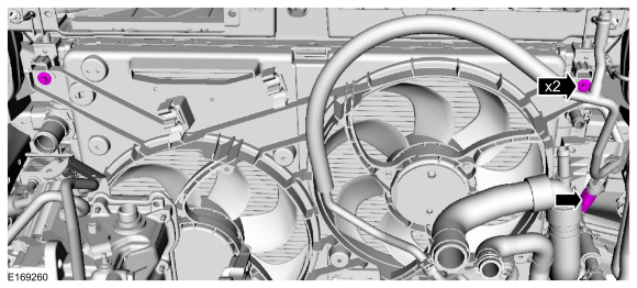
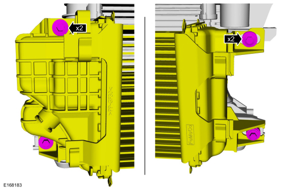
Disconnect the A/C pressure switch electrical connector and remove the bolts.
Torque:
53 lb.in (6 Nm)
-
Refer to: Jacking and Lifting - Overview (100-02 Jacking and Lifting, Description and Operation).
-
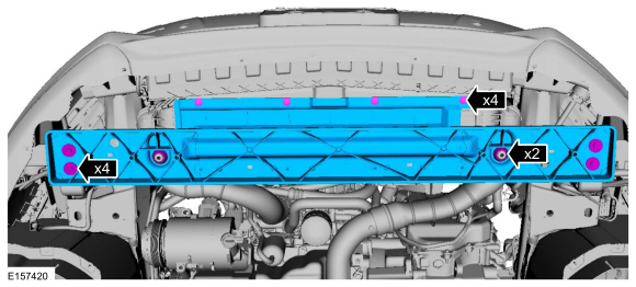
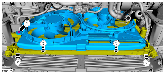
Remove the retainers and the lower radiator support.
Torque:
18 lb.ft (24 Nm)
-
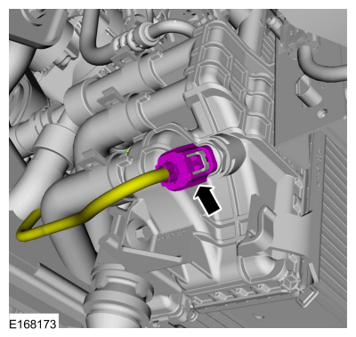
Disconnect the CAC temperature sensor electrical connector.
-
Remove the CAC bolts.
Torque:
53 lb.in (6 Nm)
-
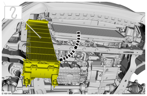
NOTE:
Position the CAC aside during cooling fan removal to prevent damage to the fins.
Position aside the CAC.
-
-
Remove the bolt.
Torque:
53 lb.in (6 Nm)
-
Raise the cooling fan above the retaining hooks.
-
Remove the cooling fan motor and shroud.
Installation
-
To install, reverse the removal procedure.
Special Tool(s) /
General Equipment
303-1556Locking Tool, Timing BeltTKIT-2010B-FLMTKIT-2010B-ROW
303-748Locking Tool, CrankshaftTKIT-2010B-FLMTKIT-2010B-ROW
Hose Clamp Remover/Installer
4 mm Drill Bit
Removal
NOTE:
The original coolant pump may not be equipped with a clutch and wiring harness connector...
Special Tool(s) /
General Equipment
Hose Clamp(s)
Removal
NOTE:
Removal steps in this procedure may contain installation details.
WARNING:
Before beginning any service procedure in this
section, refer to Safety Warnings in section 100-00 General Information...
Other information:
Removal
NOTE:
Removal steps in this procedure may contain installation details.
Roof mounted antenna
Carefully lower the rear of the headliner.
Refer to: Headliner (501-05 Interior Trim and Ornamentation, Removal and Installation).
Remove the audio unit antenna retaining bolt and retainer...
Component Location, Parking Aid - Audible
Item
Description
1
Front parking aid sensors
2
Parking aid switch (if equipped)
3
Rear speakers (part of audio system)
4
Rear parking aid sensors
5
Front speakers (part of audio system)
6
PAM (integral to the BCM
Component Location, Parking Aid - Video
Item
Description
1
..
 Coolant Pump. Removal and Installation
 Degas Bottle. Removal and Installation