Ford Fusion: Climate Control System - General Information / Condenser - 1.5L EcoBoost (118kW/160PS) – I4. Removal and Installation
Ford Fusion 2013–2020 Service Manual / Electrical / Climate Control System / Climate Control System - General Information / Condenser - 1.5L EcoBoost (118kW/160PS) – I4. Removal and Installation
Removal
NOTICE: During the removal or installation of components, cap, tape or otherwise appropriately protect all openings and tubes/fittings to prevent the ingress of dirt or other contamination. Remove caps, tape and other protective materials prior to installation.
NOTE: Removal steps in this procedure may contain installation details.
-
Recover the refrigerant. Refer to the appropriate Recovery procedure in Group 412.
-
Remove the CAC radiator.
Refer to: Charge Air Cooler (CAC) Radiator (303-12A Intake Air Distribution and Filtering - 1.5L EcoBoost (118kW/160PS) – I4, Removal and Installation).
-
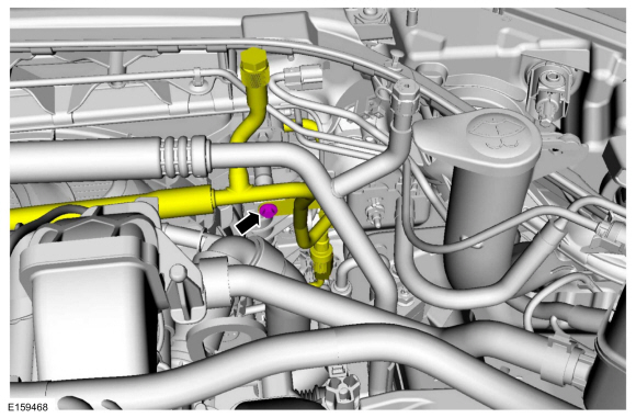
Remove the bracket bolt and position the A/C compressor outlet line bracket aside.
Torque: 62 lb.in (7 Nm)
 |
-
NOTICE: Make sure that all openings are sealed.
-
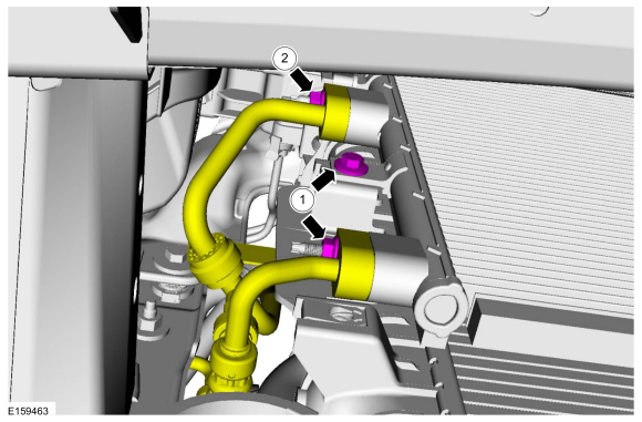
Remove the condenser outlet line nut, disconnect the
fitting and discard the O-ring seal and gasket seal. Remove the
condenser mounting bolt.
Torque: 71 lb.in (8 Nm)
-
Remove the A/C compressor outlet line nut and disconnect the fitting. Discard the O-ring seal and gasket seal.
Torque: 133 lb.in (15 Nm)
-
Make sure to cover any open ports to prevent debris from entering the system.
-
Remove the condenser outlet line nut, disconnect the
fitting and discard the O-ring seal and gasket seal. Remove the
condenser mounting bolt.
 |
-
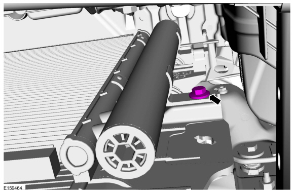
Remove the condenser mounting bolt.
Torque: 71 lb.in (8 Nm)
 |
-
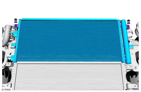
Release the tabs and remove the condenser.
 |
Installation
-
To install, reverse the removal procedure.
-
NOTICE: Only use the specified material to lubricate the seals.
Install and lubricate new O-ring seals. Refer to the appropriate Specifications in Group 412.
-
Lubricate the refrigerant system with the correct amount
of clean PAG oil. Refer to the appropriate Refrigerant Oil Adding
procedure in Group 412.
 Climate Control Housing - Vehicles With: Electronic Manual Temperature Control (EMTC). Removal and Installation
Removal
NOTE:
Removal steps in this procedure may contain installation details.
Remove the instrument panel upper section.
Refer to: Instrument Panel Upper Section (501-12 Instrument Panel and Console, Removal and Installation)...
 Condenser Outlet Line - 1.5L EcoBoost (118kW/160PS) – I4. Removal and Installation
Removal
NOTICE:
During the removal or installation of components, cap, tape
or otherwise appropriately protect all openings and tubes/fittings to
prevent the ingress of dirt or other contamination...
Other information:
Ford Fusion 2013–2020 Service Manual: Locked Seatbelt Retractor Releasing. General Procedures
Repair NOTE: If the seatbelt webbing does not extract from the seatbelt retractor from the stowed position, this may be due to a normal condition which happens when the seatbelt retracts at a high rate of speed. Follow these steps to release the seatbelt...
Ford Fusion 2013–2020 Owners Manual: Apps
The system allows you interact with select mobile apps while keeping your eyes on the road. Voice commands, your steering wheel buttons, or a quick tap on your touchscreen give you advanced control of compatible mobile apps. You can also stream your favorite music or podcasts, share your time of arrival with friends, and keep connected safely...
Categories
- Manuals Home
- 2nd Generation Ford Fusion Owners Manual
- 2nd Generation Ford Fusion Service Manual
- Steering Column Control Module (SCCM). Removal and Installation
- Powertrain
- Engine - 1.5L EcoBoost (118kW/160PS) – I4
- New on site
- Most important about car
Fuel Quality
Choosing the Right Fuel
Your vehicle is designed to operate on regular unleaded gasoline with a minimum pump (R+M)/2 octane rating of 87.
Copyright © 2025 www.fofusion2.com