Ford Fusion: Module Communications Network / Communications Network - System Operation and Component Description. Description and Operation
System Operation
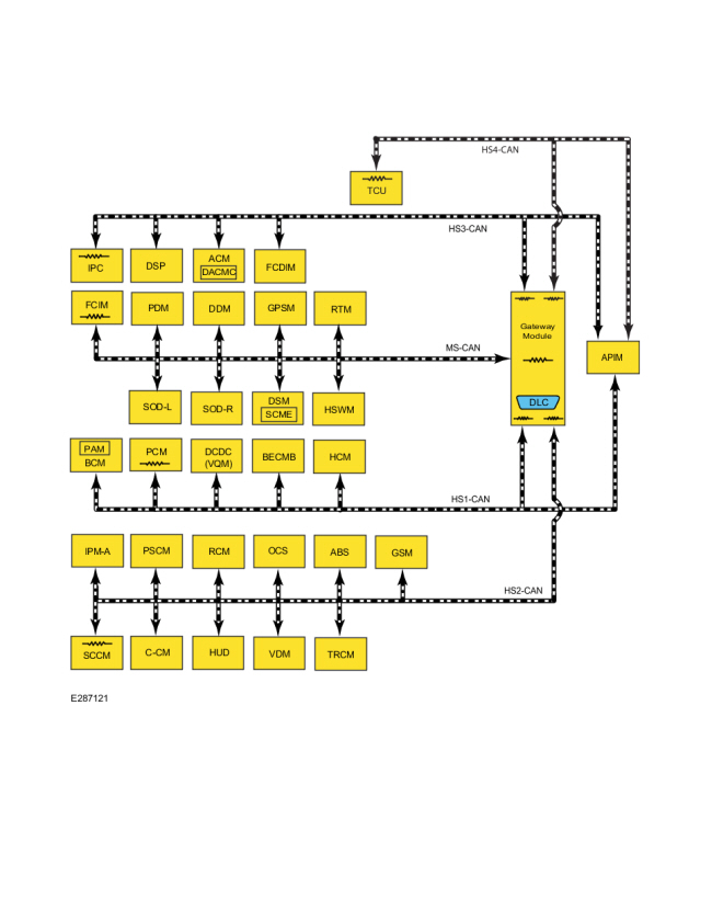
System Diagram
.jpg)
| Item | Description |
|---|---|
| 1 | BCM |
| 2 | DDM |
| 3 | PDM |
| 4 | DSP |
| 5 | ACM |
| 6 | PSCM |
| 7 | GPSM |
| 8 | IPMA |
| 9 | OCSM |
| 10 | RCM |
| 11 | PCM |
| 12 | GWM |
| 13 | FCDIM |
| 14 | DLC |
| 15 | SODL |
| 16 | SODR |
| 17 | DSM |
| 18 | HUD |
| 19 | RTM |
| 20 | FCIM |
| 21 | IPC |
| 22 | SCCM |
| 23 | ABS module |
| 24 | CCM |
| 25 | APIM |
| 26 | PAM |
| 27 | DCDC (VQM) |
| 28 | HSWM |
| 29 | BECMB |
| 30 | HCM |
| 31 | GSM |
| 32 | VDM |
| 33 | SCME |
| 34 | TRCM |
| 35 | DACMC |
| 36 | TCU |
Module Network Chart
| Module Name | Network Type | Terminating Module |
|---|---|---|
| APIM (if equipped) | HS-CAN1 | No |
| HS-CAN3 | No | |
| HS-CAN4 | No | |
| ABS module | HS-CAN2 | No |
| ACM | HS-CAN3 | No |
| BECMB | HS-CAN1 | No |
| DSP (if equipped) | HS-CAN3 | No |
| BCM | HS-CAN1 | No |
| CCM | HS-CAN2 | No |
| DACMC (if equipped, integral with ACM) | HS-CAN3 | No |
| DC/ DC (DC/DC) converter control module (VQM) (if equipped) | HS-CAN1 | No |
| DDM | MS-CAN | No |
| DSM | MS-CAN | No |
| FCIM | MS-CAN | Yes |
| FCDIM (if equipped) | HS-CAN3 | No |
| GWM | HS-CAN1 | Yes |
| HS-CAN2 | Yes | |
| HS-CAN3 | Yes | |
| MS-CAN | Yes | |
| GSM | HS-CAN2 | No |
| GPSM (if equipped) | MS-CAN | No |
| HCM (if equipped) | HS-CAN1 | No |
| HUD module (if equipped) | HS-CAN2 | No |
| HSWM (if equipped) | MS-CAN | No |
| IPC | HS-CAN3 | Yes |
| IPMA (if equipped) | HS-CAN2 | No |
| OCS | HS-CAN2 | No |
| PAM (if equipped, integral with BCM) | HS-CAN1 | No |
| PSCM | HS-CAN2 | No |
| PCM | HS-CAN1 | Yes |
| PDM | MS-CAN | No |
| RTM | MS-CAN | No |
| RCM | HS-CAN2 | No |
| SODL (if equipped) | MS-CAN | No |
| SODR (if equipped) | MS-CAN | No |
| SCME (if equipped, integral with DSM) | MS-CAN | No |
| SCCM | HS-CAN2 | Yes |
| TCU (if equipped) | HS-CAN4 | Yes |
| TRCM | HS-CAN2 | No |
| VDM | HS-CAN2 | No |
Network Termination
The CAN uses network termination to improve communication reliability. Termination modules are located at both ends of the network. As network messages are broadcast in the form of voltage signals, the network voltage signals are stabilized by the termination resistors.
Each termination module has an internal 120 ohm resistor that bridges across the positive and negative bus connection. With two 120 ohm resistors located in a parallel circuit configuration, the total network impedance, or total resistance, is 60 ohms.
Network termination improves bus message reliability by stabilizing bus voltage and eliminating electrical interference.
Gateway Module
NOTE: The GWM, communicates with the 5 controller area networks (CAN). The OBD DLC is fitted to the GWM, and is the direct interface with the scan tool.
The GWM is mounted under the driver side instrument panel. The OBD connector is fitted to the GWM. The GWM acts as a central gateway to translate messages across all 4 or 5 (optional) vehicle controller area networks (CAN), and vice versa. The GWM is the only module on this vehicle with this ability. The GWM also serves as a termination module for each of the networks to which it is connected.
The 2 module communication networks connected to the DLC are HS-CAN1 (DIAG 1) and HS-CAN2 (DIAG 2). These 2 networks communicate directly with the diagnostic scan tool. The other 2 or 3 (optional) communication networks, HS-CAN3, HS-CAN4 and MS-CAN, communicate on the network, but do not communicate directly with the diagnostic scan tool. The GWM translates the messages from these networks to the HS-CAN2 (DIAG 2), which transfers the signals to the diagnostic scan tool.
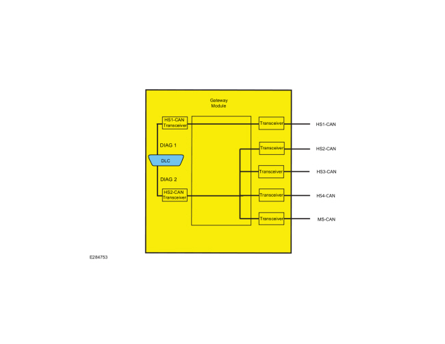
.jpg)
| Item | Description |
|---|---|
| 1 | DIAG 1 |
| 2 | DIAG 2 |
| 3 | GWM |
| 4 | Transceiver |
| 5 | DLC |
| 6 | HS2-CAN Transceiver |
| 7 | HS1-CAN Transceiver |
| 8 | Transceiver |
| 9 | Transceiver |
| 10 | Transceiver |
| 11 | Transceiver |
High Speed Controller Area Network 1 and 2 (HS-CAN1, HS-CAN2)
The HS-CAN1 and HS-CAN2 operate at a maximum data transfer speed of 500 Kbps and are designed for real time powertrain and driver feature information transfer and control. Modules on the HS-CAN1 and HS-CAN2 communicate using bussed messages. The HS-CAN uses an unshielded twisted pair cable, data bus (+) and data bus (-) circuits. In addition to scan tool communication, the HS-CAN allows sharing of information between all modules on each HS-CAN.
With the addition of more modules, network traffic has increased. This has created the need for an additional HS-CAN to manage the increased bus data carried on each network.
The GWM is used as a gateway for the messages to transfer between the scan tool and the modules on the HS-CAN1 and the modules on the HS-CAN2.
The scan tool communicates with the vehicle communication networks directly through the HS-CAN1 and HS-CAN2.
High Speed Controller Area Network 3 and 4 (HS-CAN3, HS-CAN4)
The HS-CAN3 and HS-CAN4 operate at a maximum data transfer speed of 500 Kbps and are designed for real time audio, multimedia and driver information transfer and control. Modules on the HS-CAN3 and HS-CAN4 communicate using bussed messages. HS-CAN3 and HS-CAN4 use an unshielded twisted pair cable, data bus (+) and data bus (-) circuits, and allows sharing of information between all modules on the network.
The GWM is used as a gateway for the messages to transfer between the scan tool and the modules on the HS-CAN3 and HS-CAN4.
The GWM translates the diagnostic messages from the HS-CAN2 to the HS-CAN3 and HS-CAN4 and vice versa, allowing communication between the modules on the HS-CAN3 and HS-CAN4 and the scan tool.
Medium Speed Controller Area Network (MS-CAN)
The MS-CAN operates at a maximum data transfer speed of 125 Kbps and is designed for general information transfer. Modules on the MS-CAN communicate using bussed messages. The MS-CAN uses an unshielded twisted pair cable, data bus (+) and data bus (-) circuits. In addition to scan tool communication, the MS-CAN allows sharing of information between all modules on the network.
The GWM is used as a gateway for the messages to transfer between the scan tool and the modules on the MS-CAN.
The GWM translates the diagnostic messages from the HS-CAN2 to the MS-CAN and vice versa, allowing communication between the modules on the MS-CAN and the scan tool.
Controller Area Network (CAN) Fault Tolerance
Fault Tolerance Normal Operation
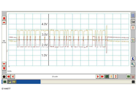
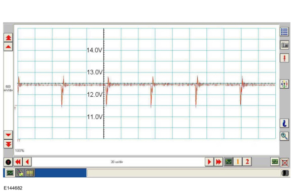
NOTE: The oscilloscope traces shown are from the IDS oscilloscope taken using the IDS pre-configured CAN settings. The traces are for both data (+) and data (-) taken simultaneously (2-channel) at a sample rate of 1 mega-sample per second (1MS/s) or greater.
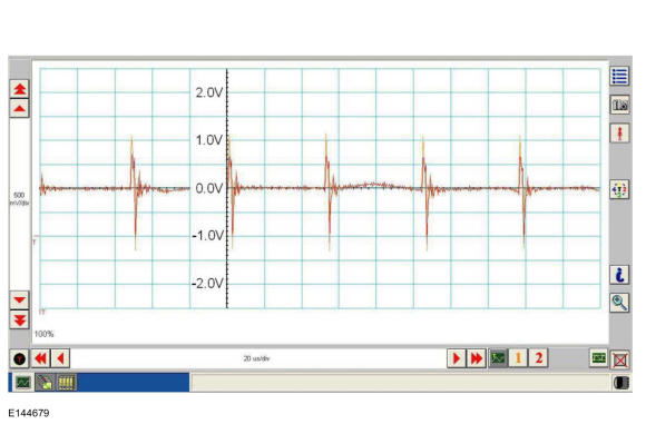
The data (+) and data (-) circuits are each regulated to approximately 2.5 volts during neutral or rested network traffic. As messages are sent on the data (+) circuit, voltage is increased by approximately 1.0 volt. Inversely, the data (-) circuit is reduced by approximately 1.0 volt when a message is sent.
Successful communication of a message can usually be identified by the slight spike at the end of a message transmission. Any signals that are significantly different than the normal CAN waveform may cause network Diagnostic Trouble Codes (DTCs) (U-codes) to set or may cause a complete network outage.
CAN Circuits Shorted Together
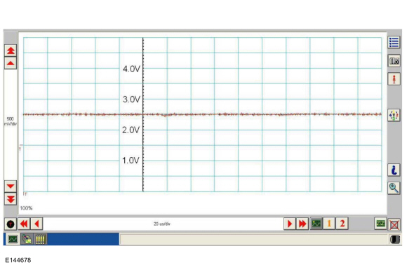
In the event the data (+) and data (-) circuits become shorted together, the signal stays at base voltage (2.5V) continuously and all communication capabilities are lost.
CAN (+) Circuit Shorted to Ground
In the event the data (+) circuit becomes shorted to ground, both the data (+) and data (-) circuits are pulled low (0V) and all communication capabilities are lost.
CAN (-) Circuit Shorted to Ground
In the event the data (-) circuit becomes shorted to ground, the data (-) circuit is pulled low (0V) and the data (+) circuit reaches near-normal peak voltage (3.0V) during communication but falls to 0V instead of normal base voltage (2.5V). Communication may continue but at a degraded level.
CAN (+) Circuit Shorted to Battery Voltage
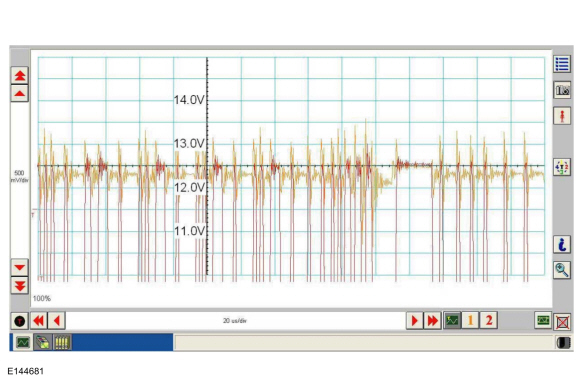
In the event the data (+) circuit becomes shorted to battery voltage, the data (+) circuit is pulled high (12V) and the data (-) circuit falls to abnormally high voltage (above 5V) during communication and reaches battery voltage (12V) for peak voltage. Communication may continue but at a degraded level.
CAN (-) Circuit Shorted to Battery Voltage
In the event the data (-) circuit becomes shorted to battery voltage, both the data (+) and data (-) circuits are pulled high (12V) and all communication capabilities are lost.
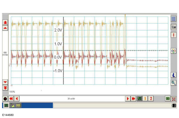
CAN Circuit Signal Corruption
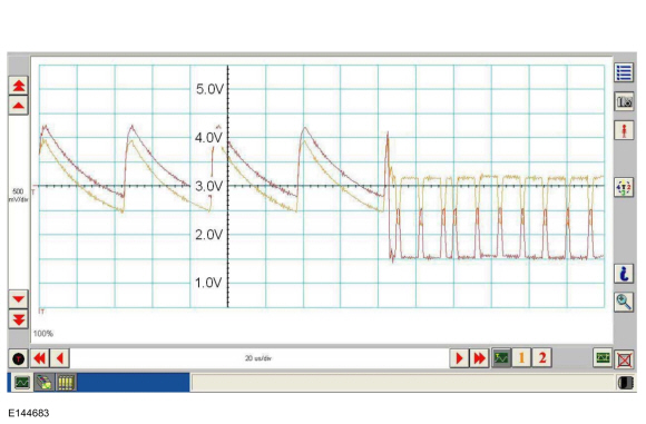
Rhythmic oscillations, inductive spikes or random interference can corrupt the network communications. The corruption signal source may be outside electrical interference such as motors or solenoids or internal interference generated from a module on the network. In some cases, an open in either the data (+) or data (-) circuit to a network module may cause the module to emit interference on the one circuit which is still connected. The trace shown is an example of a "sawtooth" pattern transmitted from a module with one open network circuit.
Other corruptions may be present when a module is intermittently powered up and down. The module on power up may initiate communication out of sync with other modules on the network causing momentary communication outages.
Controller Area Network (CAN) Multiplex Messages
The network communication message chart provides a high level description of key network messages for all CAN networks on the vehicle. This information can be used to determine which modules are involved in completing a function including display of messages, status updates and commands.
Comparative functional checks can be performed without the use of test equipment to determine if faults exist in gateway module data translation, transfer paths. Specifically, this is accomplished by verifying that another feature/function works correctly which uses the same message translation paths through the gateway module as the feature/function in question. The information listed in the communication message chart below provides the key reference information to make this possible.
Example:
The ability of the power running boards to extend when the driver door is opened confirms the ability of the gateway module to successfully translate messages from the HS-CAN1 to the MS-CAN. If this function was not operating correctly then a comparative check should be performed for another function which is completed using the same translation path but with different originating and receiving modules. REFER to the comparative example below:
| Network Message | Originating Module | Network Type | Receiving Module(s) |
|---|---|---|---|
| Driver door ajar status | BCM | HS-CAN1 |
|
| Driver door ajar status | GWM | MS-CAN |
|
In this example the path for relaying gear lever position information from the PCM to the DDM is being used for a comparative functional check. The diagnostic scan tool display of the gear lever position info in the DDM was used to verify the functionality of the HS-CAN1 to MS-CAN path.
| Network Message | Originating Module | Network Type | Receiving Module(s) |
|---|---|---|---|
| Gear lever position | PCM | HS-CAN1 |
|
| Gear lever position | GWM | MS-CAN |
|
Communication Message Chart
| Network Message | Originating Module | Network Type | Receiving Module(s) |
|---|---|---|---|
| A/C clutch status | PCM | HS-CAN1 |
|
| A/C clutch status | GWM | MS-CAN |
|
| A/C clutch status | GWM | HS-CAN3 |
|
| ABS active | ABS module | HS-CAN2 |
|
| ABS active | GWM | HS-CAN1 |
|
| ABS warning indicator request | ABS module | HS-CAN2 |
|
| ABS warning indicator request | GWM | HS-CAN3 |
|
| ABS warning indicator request | GWM | HS-CAN1 |
|
| Accelerator pedal position | PCM | HS-CAN1 |
|
| Accelerator pedal position | GWM | MS-CAN |
|
| Accelerator pedal position | GWM | HS-CAN2 |
|
| Accelerator pedal position | GWM | HS-CAN3 |
|
| ACM chime request | ACM | HS-CAN3 |
|
| ACM radio functions | ACM | HS-CAN3 |
|
| ACM radio functions | GWM | MS-CAN |
|
| ACM track information | ACM | HS-CAN3 |
|
| Adaptive cruise control brake deceleration request | CCM | HS-CAN2 |
|
| Adaptive cruise control commands | SCCM | HS-CAN2 |
|
| Adaptive cruise control commands | GWM | HS-CAN1 |
|
| Adaptive cruise control distance sensitivity | CCM | HS-CAN2 |
|
| Adaptive cruise control enabled | IPC | HS-CAN3 |
|
| Adaptive cruise control enabled | GWM | HS-CAN2 |
|
| Adaptive cruise control follow mode | PCM | HS-CAN1 |
|
| Adaptive cruise control follow mode | GWM | HS-CAN3 |
|
| Adaptive cruise control gap distance display | CCM | HS-CAN2 |
|
| Adaptive cruise control gap distance display | GWM | HS-CAN3 |
|
| Adaptive cruise control gap select | SCCM | HS-CAN2 |
|
| Adaptive cruise control gap select | GWM | HS-CAN1 |
|
| Adaptive cruise control stop mode | CCM | HS-CAN2 |
|
| Adaptive cruise control stop mode | GWM | HS-CAN3 |
|
| Adaptive cruise control stop mode request | PCM | HS-CAN1 |
|
| Adaptive cruise control stop mode request | GWM | HS-CAN2 |
|
| Adaptive cruise control warning request | CCM | HS-CAN2 |
|
| Adaptive cruise control warning request | GWM | HS-CAN3 |
|
| Adaptive headlamp fault status | HCM | HS-CAN1 |
|
| Adaptive headlamp fault status | GWM | HS-CAN3 |
|
| Airbag deployment status | RCM | HS-CAN2 |
|
| Airbag deployment status | GWM | HS-CAN1 |
|
| Airbag indicator status | IPC | HS-CAN3 |
|
| Airbag indicator status | GWM | HS-CAN2 |
|
| Airbag warning indicator request | RCM | HS-CAN2 |
|
| Airbag warning indicator request | GWM | HS-CAN3 |
|
| Ambient air temperature | PCM | HS-CAN1 |
|
| Ambient air temperature | GWM | MS-CAN |
|
| Ambient air temperature | GWM | HS-CAN3 |
|
| Ambient air temperature | GWM | HS-CAN2 |
|
| Ambient light color/intensity request | APIM | HS-CAN3 |
|
| Ambient light color/intensity request | GWM | HS-CAN1 |
|
| Audio settings | IPC | HS-CAN3 |
|
| Audio source select | IPC | HS-CAN3 |
|
| Audio system response status | ACM | HS-CAN3 |
|
| Audio system response status | GWM | MS-CAN |
|
| Audio volume status | FCIM | MS-CAN |
|
| Audio volume status | GWM | HS-CAN3 |
|
| Auto hold message request | ABS module | HS-CAN2 |
|
| Auto hold message request | GWM | HS-CAN3 |
|
| Auto hold mode indicator | ABS module | HS-CAN2 |
|
| Auto hold mode indicator | GWM | HS-CAN3 |
|
| AWD data | PCM | HS-CAN1 |
|
| AWD data | GWM | HS-CAN3 |
|
| AWD locking status | PCM | HS-CAN1 |
|
| AWD locking status | GWM | HS-CAN2 |
|
| AWD locking status | GWM | HS-CAN3 |
|
| AWD service required | PCM | HS-CAN1 |
|
| AWD service required | GWM | HS-CAN2 |
|
| AWD service required | GWM | HS-CAN3 |
|
| Battery low charge rate request | BCM | HS-CAN1 |
|
| Battery low state of charge | BCM | HS-CAN1 |
|
| Battery low state of charge | GWM | MS-CAN |
|
| Battery low state of charge | GWM | HS-CAN3 |
|
| Beltminder audio mute | IPC | HS-CAN3 |
|
| BLIS Driver LED status | DDM | MS-CAN |
|
| BLIS Passenger LED status | PDM | MS-CAN |
|
| Body service required request | BCM | HS-CAN1 |
|
| Body service required request | GWM | HS-CAN3 |
|
| Brake fluid level low message request | BCM | HS-CAN1 |
|
| Brake fluid level low message request | GWM | HS-CAN3 |
|
| Brake On/Off switch | PCM | HS-CAN1 |
|
| Brake On/Off switch | GWM | HS-CAN2 |
|
| Brake pedal applied | PCM | HS-CAN1 |
|
| Brake pedal applied | GWM | HS-CAN2 |
|
| Brake pedal applied | GWM | HS-CAN3 |
|
| Brake switch position | GSM | HS-CAN2 |
|
| Brake switch position | GWM | HS-CAN1 |
|
| Brake transmission shift lock status | BCM | HS-CAN1 |
|
| Brake transmission shift lock status | GWM | HS-CAN2 |
|
| Brake (red) warning indicator request | ABS module | HS-CAN2 |
|
| Brake (red) warning indicator request | GWM | HS-CAN3 |
|
| Brake (red) warning indicator request | BCM | HS-CAN1 |
|
| Brake (red) warning indicator request | GWM | HS-CAN3 |
|
| Brake warning indicator request | ABS module | HS-CAN2 |
|
| Brake warning indicator request | GWM | HS-CAN3 |
|
| Camera defog request | IPMA | HS-CAN2 |
|
| Camera defog request | GWM | HS-CAN3 |
|
| Camera defog request | GWM | MS-CAN |
|
| Camera settings | BCM | HS-CAN1 |
|
| Camera settings | GWM | HS-CAN3 |
|
| Camera settings request | APIM | HS-CAN3 |
|
| Camera settings request | GWM | HS-CAN1 |
|
| Charging system indication request | BCM | HS-CAN1 |
|
| Charging system indication request | GWM | HS-CAN3 |
|
| Check fuel fill inlet message request | PCM | HS-CAN1 |
|
| Check fuel fill inlet message request | GWM | HS-CAN3 |
|
| Child lock message display request | BCM | HS-CAN1 |
|
| Child lock message display request | GWM | MS-CAN |
|
| Child lock message display request | GWM | HS-CAN3 |
|
| Child lock request | DDM | MS-CAN |
|
| Child lock request | GWM | HS-CAN1 |
|
| Chime source | IPC | HS-CAN3 |
|
| Climate control button status | FCIM | MS-CAN |
|
| Climate control button status | GWM | HS-CAN3 |
|
| Climate control temperature request | FCIM | MS-CAN |
|
| Climate control temperature request | GWM | HS-CAN1 |
|
| Collision avoidance and driver support camera blocked warning | CCM | HS-CAN2 |
|
| Collision avoidance and driver support camera blocked warning | GWM | HS-CAN3 |
|
| Collision avoidance and driver support camera status | IPMA | HS-CAN2 |
|
| Collision avoidance and driver support chime request | CCM | HS-CAN2 |
|
| Collision avoidance and driver support chime request | GWM | HS-CAN3 |
|
| Collision avoidance and driver support radar blocked warning | CCM | HS-CAN2 |
|
| Collision avoidance and driver support radar blocked warning | GWM | HS-CAN3 |
|
| Collision avoidance and driver support radar status | CCM | HS-CAN2 |
|
| Collision avoidance chime request | CCM | HS-CAN2 |
|
| Collision avoidance chime request | GWM | HS-CAN3 |
|
| Collision mitigation by braking brake precharge | CCM | HS-CAN2 |
|
| Collision mitigation by braking deceleration | CCM | HS-CAN2 |
|
| Collision mitigation by braking denied | ABS module | HS-CAN2 |
|
| Collision mitigation by braking denied | GWM | HS-CAN1 |
|
| Collision mitigation by braking event status | CCM | HS-CAN2 |
|
| Collision mitigation by braking event status | GWM | HS-CAN3 |
|
| Collision mitigation by braking request | CCM | HS-CAN2 |
|
| Collision mitigation by braking request | GWM | HS-CAN1 |
|
| Collision mitigation by braking status | PCM | HS-CAN1 |
|
| Collision mitigation by braking status | GWM | HS-CAN2 |
|
| Compass direction (touchscreen) | APIM | HS-CAN1 |
|
| Compass direction (touchscreen) | GWM | HS-CAN3 |
|
| Crash event status | BCM | HS-CAN1 |
|
| Crash event status | GWM | MS-CAN |
|
| Cross traffic alert left status | SODL | MS-CAN |
|
| Cross traffic alert left status | GWM | HS-CAN3 |
|
| Cross traffic alert request | IPC | HS-CAN3 |
|
| Cross traffic alert request | GWM | MS-CAN |
|
| Cross traffic alert right status | SODR | MS-CAN |
|
| Cross traffic alert right status | GWM | HS-CAN3 |
|
| Cruise control button status | CCM | HS-CAN2 |
|
| Cruise control button status | GWM | HS-CAN1 |
|
| Cruise control mode | PCM | HS-CAN1 |
|
| Cruise control mode | GWM | HS-CAN3 |
|
| Cruise control override | PCM | HS-CAN1 |
|
| Cruise control override | GWM | HS-CAN3 |
|
| Cruise control override | GWM | HS-CAN2 |
|
| Cruise control service required | CCM | HS-CAN2 |
|
| Cruise control service required | GWM | HS-CAN3 |
|
| Cruise control set speed | PCM | HS-CAN1 |
|
| Cruise control set speed | GWM | HS-CAN3 |
|
| Cruise control status | PCM | HS-CAN1 |
|
| Cruise control status | GWM | HS-CAN3 |
|
| Cruise control status | GWM | HS-CAN2 |
|
| Cruise control switch command | SCCM | HS-CAN2 |
|
| Cruise control switch command | GWM | HS-CAN1 |
|
| Date and time adjustment request | FCDIM | HS-CAN3 |
|
| Date/time settings | APIM | HS-CAN3 |
|
| Day/night status | BCM | HS-CAN1 |
|
| Day/night status | GWM | MS-CAN |
|
| Day/night status | GWM | HS-CAN3 |
|
| Day/night status | GWM | HS-CAN2 |
|
| Decklid ajar status | BCM | HS-CAN1 |
|
| Decklid ajar status | GWM | HS-CAN2 |
|
| Decklid ajar status | GWM | HS-CAN3 |
|
| Display language request | APIM | HS-CAN3 |
|
| Display language status | FCDIM | HS-CAN3 |
|
| Display speed offset data | IPC | HS-CAN3 |
|
| Display speed offset data | GWM | HS-CAN1 |
|
| Display speed offset data | GWM | HS-CAN2 |
|
| Do not disturb override status | IPC | HS-CAN3 |
|
| Door ajar status | BCM | HS-CAN1 |
|
| Door ajar status | GWM | HS-CAN2 |
|
| Door ajar status | GWM | HS-CAN3 |
|
| Door ajar status | GWM | HS-CAN4 |
|
| Door lock switch status | DDM | MS-CAN |
|
| Door lock switch status | GWM | HS-CAN1 |
|
| Driver door ajar status | BCM | HS-CAN1 |
|
| Driver door ajar status | GWM | HS-CAN2 |
|
| Driver door ajar status | GWM | HS-CAN3 |
|
| Driver door lock switch status | DDM | MS-CAN |
|
| Driver door lock switch status | GWM | HS-CAN1 |
|
| Driver performance mode display | PCM | HS-CAN1 |
|
| Driver performance mode display | GWM | HS-CAN3 |
|
| Driver safety belt buckle status | RCM | HS-CAN2 |
|
| Driver safety belt buckle status | GWM | HS-CAN3 |
|
| Driver safety belt buckle status | GWM | HS-CAN1 |
|
| DSP chime request | DSP | HS-CAN3 |
|
| eCall confirmation | APIM | HS-CAN1 |
|
| eCall confirmation | GWM | HS-CAN2 |
|
| eCall notification | RCM | HS-CAN2 |
|
| eCall notification | GWM | HS-CAN1 |
|
| Electrical power status | PCM | HS-CAN1 |
|
| Electrical power status | GWM | MS-CAN |
|
| Electrical power status | GWM | HS-CAN2 |
|
| Engine coolant temperature data | PCM | HS-CAN1 |
|
| Engine coolant temperature data | GWM | HS-CAN3 |
|
| Engine disable status | PCM | HS-CAN1 |
|
| Engine disable status | GWM | HS-CAN2 |
|
| Engine disable status | GWM | MS-CAN |
|
| Engine oil life | PCM | HS-CAN1 |
|
| Engine oil life | GWM | HS-CAN3 |
|
| Engine oil life data reset | IPC | HS-CAN3 |
|
| Engine oil life data reset | GWM | HS-CAN1 |
|
| Engine overheat indication request | PCM | HS-CAN1 |
|
| Engine overheat indication request | GWM | HS-CAN3 |
|
| Engine rpm data | PCM | HS-CAN1 |
|
| Engine rpm data | GWM | HS-CAN3 |
|
| Engine service required request | PCM | HS-CAN1 |
|
| Engine service required request | GWM | HS-CAN2 |
|
| Engine service required request | GWM | HS-CAN3 |
|
| English/metric mode | IPC | HS-CAN3 |
|
| English/metric mode | GWM | HS-CAN1 |
|
| English/metric mode | GWM | MS-CAN |
|
| EPAS data | PSCM | HS-CAN2 |
|
| EPAS data | GWM | HS-CAN1 |
|
| EPAS failure | PSCM | HS-CAN2 |
|
| EPAS failure | GWM | HS-CAN1 |
|
| EPAS failure | GWM | HS-CAN3 |
|
| ePRNDL mode | IPC | HS-CAN3 |
|
| ePRNDL mode | GWM | HS-CAN1 |
|
| ePRNDL mode | GWM | HS-CAN2 |
|
| Evaporator temperature | FCIM | MS-CAN |
|
| Evaporator temperature | GWM | HS-CAN1 |
|
| Exterior ambient air temperature data | FCIM | MS-CAN |
|
| Exterior ambient air temperature data | GWM | HS-CAN2 |
|
| Exterior ambient air temperature data | GWM | HS-CAN1 |
|
| Exterior ambient air temperature data | GWM | HS-CAN3 |
|
| FCIM bezel diagnostic status | FCIM | MS-CAN |
|
| FCIM bezel diagnostic status | GWM | HS-CAN3 |
|
| FCIM button state | FCIM | MS-CAN |
|
| FCIM button state | GWM | HS-CAN3 |
|
| Fog lamp indicator request | BCM | HS-CAN1 |
|
| Fog lamp indicator request | GWM | HS-CAN3 |
|
| Forward collision chime request | CCM | HS-CAN2 |
|
| Forward collision chime request | GWM | HS-CAN3 |
|
| Forward collision warning message request | CCM | HS-CAN2 |
|
| Forward collision warning message request | GWM | HS-CAN3 |
|
| Front passenger detect status | RCM | HS-CAN2 |
|
| Front passenger detect status | GWM | HS-CAN3 |
|
| Front passenger safety belt buckle status | RCM | HS-CAN2 |
|
| Front passenger safety belt buckle status | GWM | HS-CAN3 |
|
| Front window heater status | FCIM | MS-CAN |
|
| Front window heater status | GWM | HS-CAN2 |
|
| Front wiper status | SCCM | HS-CAN2 |
|
| Front wiper status | GWM | HS-CAN1 |
|
| Front wiper status | GWM | MS-CAN |
|
| Fuel flow level volume display | PCM | HS-CAN1 |
|
| Fuel flow level volume display | GWM | HS-CAN3 |
|
| Fuel pump power status | BCM | HS-CAN1 |
|
| Gear button data | GSM | HS-CAN2 |
|
| Gear button data | GWM | HS-CAN1 |
|
| Gear command | PCM | HS-CAN1 |
|
| Gear command | GWM | HS-CAN2 |
|
| Gear confirmation | TRCM | HS-CAN2 |
|
| Gear confirmation | GWM | HS-CAN1 |
|
| GPS compass direction | GPSM | MS-CAN |
|
| GPS compass direction | GWM | HS-CAN3 |
|
| Gear request | GSM | HS-CAN2 |
|
| Gear request | GWM | HS-CAN1 |
|
| Gearshift module service required | GSM | HS-CAN2 |
|
| Gearshift module service required | GWM | HS-CAN1 |
|
| Gearshift module service required | GWM | HS-CAN3 |
|
| GPS data | GPSM | MS-CAN |
|
| GPS data | GWM | HS-CAN3 |
|
| Head up display flash command | CCM | HS-CAN2 |
|
| Head up display fault | HUD module | HS-CAN2 |
|
| Head up display fault | GWM | HS-CAN3 |
|
| Head up display flash rate | CCM | HS-CAN2 |
|
| Head up display request | CCM | HS-CAN2 |
|
| Head up display status | HUD module | HS-CAN2 |
|
| Headlamp flash to pass status | SCCM | HS-CAN2 |
|
| Headlamp flash to pass status | GWM | HS-CAN1 |
|
| Headlamp low beam out | BCM | HS-CAN1 |
|
| Headlamp low beam out | GWM | HS-CAN3 |
|
| Headlamp low status | BCM | HS-CAN1 |
|
| Headlamp low status | GWM | HS-CAN2 |
|
| Headlamp switch status | BCM | HS-CAN1 |
|
| Headlamp switch status | GWM | HS-CAN3 |
|
| Headlamp switch status | GWM | HS-CAN2 |
|
| Headlamp switch status | GWM | MS-CAN |
|
| High beam status | BCM | HS-CAN1 |
|
| High beam status | GWM | HS-CAN3 |
|
| Hill start assist request | IPC | HS-CAN3 |
|
| Hill start assist request | GWM | HS-CAN2 |
|
| Hill start assist status | ABS module | HS-CAN2 |
|
| Hill start assist status | GWM | HS-CAN1 |
|
| Hill start assist status | GWM | HS-CAN3 |
|
| Hood ajar status | BCM | HS-CAN1 |
|
| Hood ajar status | GWM | HS-CAN3 |
|
| HVAC A/C request | FCIM | MS-CAN |
|
| HVAC A/C request | GWM | HS-CAN1 |
|
| HVAC front/rear blower status | FCIM | MS-CAN |
|
| HVAC front/rear blower status | GWM | HS-CAN1 |
|
| HVAC heater core temperature | PCM | HS-CAN1 |
|
| HVAC heater core temperature | GWM | MS-CAN |
|
| HVAC heater core temperature | GWM | HS-CAN3 |
|
| HVAC temperature request | FCIM | MS-CAN |
|
| HVAC temperature request | GWM | HS-CAN1 |
|
| Ignition key type | BCM | HS-CAN1 |
|
| Ignition key type | GWM | MS-CAN |
|
| Ignition key type | GWM | HS-CAN2 |
|
| Ignition key type | GWM | HS-CAN3 |
|
| Ignition status | BCM | HS-CAN1 |
|
| Ignition status | GWM | HS-CAN3 |
|
| Ignition status | GWM | MS-CAN |
|
| Ignition status | GWM | HS-CAN2 |
|
| Ignition status | GWM | HS-CAN4 |
|
| Illumination dimming level | BCM | HS-CAN1 |
|
| Illumination dimming level | GWM | MS-CAN |
|
| Illumination dimming level | GWM | HS-CAN3 |
|
| Illumination dimming level | GWM | HS-CAN2 |
|
| Input controller interface button data | SCCM | HS-CAN2 |
|
| Input controller interface button data | GWM | HS-CAN3 |
|
| Intelligent Access (IA) system message display | BCM | HS-CAN1 |
|
| Intelligent Access (IA) system message display | GWM | HS-CAN3 |
|
| IPC chime request | IPC | HS-CAN3 |
|
| Key-in-ignition status | BCM | HS-CAN1 |
|
| Key-in-ignition status | GWM | HS-CAN2 |
|
| Key-in-ignition status | GWM | HS-CAN3 |
|
| Lane departure warning chime request | IPMA | HS-CAN2 |
|
| Lane departure warning chime request | GWM | HS-CAN3 |
|
| Lane departure warning indicator request | IPMA | HS-CAN2 |
|
| Lane departure warning indicator request | GWM | HS-CAN3 |
|
| Lane keep assist angle request | IPMA | HS-CAN2 |
|
| Lane keep assist hands off status | PSCM | HS-CAN2 |
|
| Lane keep assist hands off status | GWM | HS-CAN3 |
|
| Lane keep assist status | IPMA | HS-CAN2 |
|
| Lane keep assist status | GWM | HS-CAN3 |
|
| Language update status | IPC | HS-CAN3 |
|
| Left turn lamp request | BCM | HS-CAN1 |
|
| Left turn lamp request | GWM | HS-CAN2 |
|
| Life cycle mode | BCM | HS-CAN1 |
|
| Life cycle mode | GWM | HS-CAN3 |
|
| Life cycle mode | GWM | HS-CAN4 |
|
| Manual mirror override | DDM | MS-CAN |
|
| Memory feedback request | DSM | MS-CAN |
|
| Memory feedback request | GWM | HS-CAN3 |
|
| Memory seat switch status | DDM | MS-CAN |
|
| Message center display | IPC | HS-CAN3 |
|
| Message center display | GWM | HS-CAN2 |
|
| Message center display | GWM | HS-CAN1 |
|
| Message center display | GWM | MS-CAN |
|
| Message center feature configuration | IPC | HS-CAN3 |
|
| Message center feature configuration | GWM | HS-CAN2 |
|
| Message center feature configuration | GWM | HS-CAN1 |
|
| Message center feature configuration | GWM | MS-CAN |
|
| MIL request | PCM | HS-CAN1 |
|
| MIL request | GWM | HS-CAN2 |
|
| MIL request | GWM | HS-CAN3 |
|
| Mirror heat on request | FCIM | MS-CAN |
|
| Multimedia player data request | IPC | HS-CAN3 |
|
| Multimedia player total play time status | APIM | HS-CAN3 |
|
| MyKey® change key type request | IPC | HS-CAN3 |
|
| MyKey® change key type request | GWM | HS-CAN1 |
|
| MyKey® code status | BCM | HS-CAN1 |
|
| MyKey® code status | GWM | HS-CAN3 |
|
| MyKey® volume limit status | IPC | HS-CAN3 |
|
| Object entrapped message | OCSM | HS-CAN2 |
|
| Object entrapped message | GWM | HS-CAN3 |
|
| OCS sensor data | OCSM | HS-CAN2 |
|
| OCS sensor data | GWM | MS-CAN |
|
| OCS fault status | OCSM | HS-CAN2 |
|
| OCS serial number | OCSM | HS-CAN2 |
|
| OCS vehicle calibration data | OCSM | HS-CAN2 |
|
| Odometer count | PCM | HS-CAN1 |
|
| Odometer count | GWM | HS-CAN3 |
|
| Odometer master value | IPC | HS-CAN3 |
|
| Odometer master value | GWM | HS-CAN2 |
|
| Odometer master value | GWM | HS-CAN1 |
|
| Odometer master value | GWM | HS-CAN4 |
|
| Odometer trip programming data | IPC | HS-CAN3 |
|
| Odometer trip programming data | GWM | HS-CAN1 |
|
| Oil pressure warning indicator request | PCM | HS-CAN1 |
|
| Oil pressure warning indicator request | GWM | HS-CAN3 |
|
| Parking aid angle control status | PSCM | HS-CAN2 |
|
| Parking aid angle control status | GWM | HS-CAN1 |
|
| Parking aid chime request | PAM | HS-CAN1 |
|
| Parking aid chime request | GWM | HS-CAN3 |
|
| Parking aid enable request | IPC | HS-CAN3 |
|
| Parking aid enable request | GWM | HS-CAN1 |
|
| Parking aid enable status | BCM | HS-CAN1 |
|
| Parking aid enable status | GWM | HS-CAN3 |
|
| Parking aid status | PAM | HS-CAN1 |
|
| Parking aid status | GWM | HS-CAN3 |
|
| Parking aid sensor status | PAM | HS-CAN1 |
|
| Parking aid sensor status | GWM | HS-CAN3 |
|
| Parking brake actual | ABS module | HS-CAN2 |
|
| Parking brake actual | GWM | HS-CAN1 |
|
| Parking brake status | ABS module | HS-CAN2 |
|
| Parking brake status | GWM | MS-CAN |
|
| Parking brake status | GWM | HS-CAN1 |
|
| Parking brake chime request | BCM | HS-CAN1 |
|
| Parking brake chime request | GWM | HS-CAN3 |
|
| Parking brake indicator request | ABS module | HS-CAN2 |
|
| Parking brake indicator request | GWM | HS-CAN3 |
|
| Parklamp status | BCM | HS-CAN1 |
|
| Parklamp status | GWM | HS-CAN3 |
|
| Park lamp status | GWM | MS-CAN |
|
| Passenger door lock switch status | PDM | MS-CAN |
|
| Passenger door lock switch status | GWM | HS-CAN1 |
|
| Passenger mirror command | DDM | MS-CAN |
|
| Passenger rear window lock command | DDM | MS-CAN |
|
| Passenger restraints indicator request | RCM | HS-CAN2 |
|
| Passenger restraints indicator request | GWM | MS-CAN |
|
| Passenger window command | DDM | MS-CAN |
|
| PATS control command | BCM | HS-CAN1 |
|
| PATS start request target data | PCM | HS-CAN1 |
|
| PATS start request target data | GWM | HS-CAN2 |
|
| PATS target immobilization command | PCM | HS-CAN1 |
|
| PATS target immobilization command | GWM | HS-CAN2 |
|
| PATS target immobilization status | PCM | HS-CAN1 |
|
| PATS target immobilization status | GWM | HS-CAN2 |
|
| Perimeter alarm chime request | BCM | HS-CAN1 |
|
| Perimeter alarm chime request | GWM | HS-CAN3 |
|
| Power mode | BCM | HS-CAN1 |
|
| Power mode | GWM | HS-CAN3 |
|
| Power pack status | PCM | HS-CAN1 |
|
| Power pack status | GWM | HS-CAN3 |
|
| Powertrain cooling message request | PCM | HS-CAN1 |
|
| Powertrain cooling message request | GWM | HS-CAN3 |
|
| Powertrain data | PCM | HS-CAN1 |
|
| Powertrain data | GWM | HS-CAN3 |
|
| Power up chime modules | IPC | HS-CAN3 |
|
| Puddle lamp activation | BCM | HS-CAN1 |
|
| Puddle lamp activation | GWM | MS-CAN |
|
| RCM serial number | RCM | HS-CAN2 |
|
| Refuel system status display | PCM | HS-CAN1 |
|
| Refuel system status display | GWM | HS-CAN3 |
|
| Restraint impact event status | RCM | HS-CAN2 |
|
| Restraint impact event status | GWM | HS-CAN3 |
|
| Restraint impact event status | GWM | HS-CAN1 |
|
| Restraint impact event status | GWM | MS-CAN |
|
| Restraint indicator lamp status | IPC | HS-CAN3 |
|
| Restraint indicator lamp status | FCIM | MS-CAN |
|
| Restraint indicator lamp status | GWM | HS-CAN2 |
|
| Reverse gear state | PCM | HS-CAN1 |
|
| Reverse gear state | GWM | MS-CAN |
|
| Reverse gear state | GWM | HS-CAN2 |
|
| Reverse gear state | GWM | HS-CAN3 |
|
| Right turn lamp request | BCM | HS-CAN1 |
|
| Right turn lamp request | GWM | HS-CAN2 |
|
| RKE data | RTM | MS-CAN |
|
| RKE data | GWM | HS-CAN1 |
|
| Seat memory command | DSM | MS-CAN |
|
| Side obstacle detect status-left | SODL | MS-CAN |
|
| Side obstacle detect status-right | SODR | MS-CAN |
|
| Side obstacle detect status | GWM | HS-CAN2 |
|
| Side obstacle sensor status-left | SODL | MS-CAN |
|
| Side obstacle sensor status-left | GWM | HS-CAN3 |
|
| Side obstacle sensor status-right | SODR | MS-CAN |
|
| Side obstacle sensor status-right | GWM | HS-CAN3 |
|
| Stability control brake active | ABS module | HS-CAN2 |
|
| Stability control brake active | GWM | HS-CAN1 |
|
| Stability-traction control brake available | ABS module | HS-CAN2 |
|
| Stability-traction control chime request | ABS module | HS-CAN2 |
|
| Stability-traction control chime request | GWM | HS-CAN3 |
|
| Stability-traction control disabled indicator request | ABS module | HS-CAN2 |
|
| Stability-traction control disabled indicator request | GWM | HS-CAN3 |
|
| Stability-traction control indicator request | ABS module | HS-CAN2 |
|
| Stabililty-traction control indicator request | GWM | HS-CAN3 |
|
| Stability-traction control indicator request | GWM | HS-CAN1 |
|
| Starting system fault message request | PCM | HS-CAN1 |
|
| Starting system fault message request | GWM | HS-CAN3 |
|
| SCCM button state | SCCM | HS-CAN2 |
|
| SCCM button state | GWM | HS-CAN3 |
|
| Steering column position switch status | SCCM | HS-CAN2 |
|
| Steering column position switch status | GWM | MS-CAN |
|
| Steering wheel angle control | PSCM | HS-CAN2 |
|
| Steering wheel angle control | GWM | HS-CAN1 |
|
| Steering wheel angle sensor | PSCM | HS-CAN2 |
|
| Steering wheel angle sensor | GWM | HS-CAN1 |
|
| Steering wheel controls data | SCCM | HS-CAN2 |
|
| Steering wheel controls data | GWM | HS-CAN3 |
|
| Steering wheel lock message request | BCM | HS-CAN1 |
|
| Steering wheel lock message request | GWM | HS-CAN3 |
|
| Stop/start driver mode button press | FCIM | MS-CAN |
|
| Stop/start driver mode button press | GWM | HS-CAN1 |
|
| Stop/start driver mode indicator | PCM | HS-CAN1 |
|
| Stop/start driver mode indicator | GWM | MS-CAN |
|
| Stop/start driver mode indicator | GWM | HS-CAN3 |
|
| Stop/start driver mode request | IPC | HS-CAN3 |
|
| Stop/start driver mode request | GWM | HS-CAN1 |
|
| Stop/start message request | PCM | HS-CAN1 |
|
| Stop/start message request | GWM | HS-CAN3 |
|
| Stop/start standby indicator request | PCM | HS-CAN1 |
|
| Stop/start standby indicator request | GWM | MS-CAN |
|
| Stop/start standby indicator request | GWM | HS-CAN3 |
|
| Tire pressure data | BCM | HS-CAN1 |
|
| Tire pressure data | GWM | HS-CAN3 |
|
| Tire pressure information | BCM | HS-CAN1 |
|
| Tire pressure information | GWM | MS-CAN |
|
| Tire pressure reset request | IPC | HS-CAN3 |
|
| Tire pressure reset request | GWM | HS-CAN1 |
|
| Tire pressure status | BCM | HS-CAN1 |
|
| Tire pressure status | GWM | MS-CAN |
|
| Tire pressure status | GWM | HS-CAN3 |
|
| Tire pressure warning indicator | BCM | HS-CAN1 |
|
| Tire pressure warning indicator | GWM | HS-CAN3 |
|
| Traction control mode | ABS module | HS-CAN2 |
|
| Traction control mode | GWM | HS-CAN1 |
|
| Traction control mode | GWM | HS-CAN3 |
|
| Traffic recognition data | IPMA | HS-CAN2 |
|
| Traffic recognition data | GWM | HS-CAN3 |
|
| Transmission fault message request | PCM | HS-CAN1 |
|
| Transmission fault message request | GWM | HS-CAN3 |
|
| Transmission gear display actual | PCM | HS-CAN1 |
|
| Transmission gear display actual | GWM | HS-CAN3 |
|
| Transmission gear display actual | GWM | HS-CAN2 |
|
| Transmission lever request | PCM | HS-CAN1 |
|
| Transmission lever request | GWM | HS-CAN2 |
|
| Transmission service required | PCM | HS-CAN1 |
|
| Transmission service required | GWM | HS-CAN2 |
|
| Transmission service required | GWM | HS-CAN3 |
|
| Transmission shift indicator | PCM | HS-CAN1 |
|
| Transmission shift indicator | GWM | HS-CAN3 |
|
| Transmission shift mode display | PCM | HS-CAN1 |
|
| Transmission shift mode display | GWM | HS-CAN3 |
|
| Transmission shift mode request | PCM | HS-CAN1 |
|
| Transmission shift mode request | GWM | HS-CAN3 |
|
| TRCM service required | TRCM | HS-CAN2 |
|
| TRCM service required | GWM | HS-CAN3 |
|
| Turn indication status | BCM | HS-CAN1 |
|
| Turn indication status | GWM | HS-CAN3 |
|
| Turn signal status | SCCM | HS-CAN2 |
|
| Turn signal status | GWM | HS-CAN3 |
|
| Turn signal switch status | SCCM | HS-CAN2 |
|
| Turn signal switch status | GWM | HS-CAN1 |
|
| VDM suspension data | VDM | HS-CAN2 |
|
| VDM suspension data | GWM | HS-CAN1 |
|
| Vehicle configuration data | BCM | HS-CAN1 |
|
| Vehicle configuration data | GWM | HS-CAN2 |
|
| Vehicle configuration data | GWM | MS-CAN |
|
| Vehicle configuration data | GWM | HS-CAN3 |
|
| Vehicle dynamic data display | VDM | HS-CAN2 |
|
| Vehicle dynamic data display | GWM | HS-CAN3 |
|
| Vehicle dynamic module configuration data | VDM | HS-CAN2 |
|
| Vehicle dynamic module configuration data | GWM | HS-CAN3 |
|
| Vehicle dynamics SOS | ABS module | HS-CAN2 |
|
| Vehicle dynamics SOS | GWM | HS-CAN3 |
|
| Vehicle emergency data | RCM | HS-CAN2 |
|
| Vehicle emergency data | GWM | HS-CAN3 |
|
| Vehicle lateral acceleration | ABS module | HS-CAN2 |
|
| Vehicle lateral acceleration | RCM | HS-CAN2 |
|
| Vehicle lateral acceleration | GWM | HS-CAN1 |
|
| Vehicle lock status | BCM | HS-CAN1 |
|
| Vehicle lock status | GWM | HS-CAN2 |
|
| Vehicle lock status | GWM | HS-CAN4 |
|
| Vehicle longitudinal acceleration | RCM | HS-CAN2 |
|
| Vehicle longitudinal acceleration | GWM | HS-CAN1 |
|
| Vehicle longitudinal acceleration | ABS module | HS-CAN2 |
|
| Vehicle longitudinal acceleration | GWM | HS-CAN1 |
|
| Vehicle mode | BCM | HS-CAN1 |
|
| Vehicle mode | GWM | MS-CAN |
|
| Vehicle mode | GWM | HS-CAN2 |
|
| Vehicle mode | GWM | HS-CAN3 |
|
| Vehicle speed | GWM | HS-CAN3 |
|
| Vehicle speed | GWM | HS-CAN3 |
|
| Vehicle speed | GWM | MS-CAN |
|
| Vehicle speed | PCM | HS-CAN1 |
|
| Vehicle speed | GWM | HS-CAN2 |
|
| Vehicle system status | BCM | HS-CAN1 |
|
| Vehicle system status | GWM | HS-CAN3 |
|
| Vehicle temperature display units | APIM | HS-CAN3 |
|
| Vehicle trip display units | APIM | HS-CAN3 |
|
| Vehicle trip summary display | IPC | HS-CAN3 |
|
| Vehicle yaw rate | ABS module | HS-CAN2 |
|
| Vehicle yaw rate | GWM | HS-CAN1 |
|
| Vehicle yaw rate | GWM | HS-CAN3 |
|
| Vehicle yaw rate | GWM | MS-CAN |
|
| Vehicle yaw rate | RCM | HS-CAN2 |
|
| Vehicle yaw rate | GWM | MS-CAN |
|
| Voice recognition bluetooth response data | APIM | HS-CAN3 |
|
| Voltage stability level status | DC/DC (VQM) | HS-CAN1 |
|
| Wheel rotation count | ABS module | HS-CAN2 |
|
| Wheel rotation count | GWM | HS-CAN1 |
|
| Wheel rotation count | GWM | MS-CAN |
|
| Wheel rotation count | GWM | HS-CAN3 |
|
| Wheel rotation direction | ABS module | HS-CAN2 |
|
| Wheel rotation direction | GWM | HS-CAN1 |
|
| Wheel rotation direction | GWM | MS-CAN |
|
| Wheel rotation direction | GWM | HS-CAN3 |
|
| Wheel speed data | ABS module | HS-CAN2 |
|
| Wheel speed data | GWM | HS-CAN1 |
|
| Window lockout status | BCM | HS-CAN1 |
|
| Window lockout status | GWM | MS-CAN |
|
| Window position status | PDM | MS-CAN |
|
| Window position status | DDM | MS-CAN |
|
| Window position status | GWM | HS-CAN1 |
|
| Wi-Fi settings | APIM | HS-CAN4 |
|
 Communications Network - Overview. Description and Operation
Overview
Multiplexing
is a method of sending 2 or more signals simultaneously over a single
circuit. Multiplexing allows 2 or more electronic modules (nodes) to
communicate over a twisted wire pair [data (+) and data (-)] network...
 Communications Network. Diagnosis and Testing
DTC Chart: Gateway Module (GWM)
Diagnostics in this manual assume a certain skill level and knowledge of Ford-specific diagnostic practices. REFER to: Diagnostic Methods (100-00 General Information, Description and Operation)...
Other information:
Ford Fusion 2013–2020 Service Manual: Seat Heater Mat Installation. General Procedures
Repair NOTE: Click here to view a video version of the seat heater mat removal and installation. View NOTE: Always install a new heater mat. NOTE: During installation, it is allowable to adhere a new heater mat to any adhesive left behind on the foam...
Ford Fusion 2013–2020 Service Manual: Blind Spot Information System. Diagnosis and Testing
DTC Chart(s) Diagnostics in this manual assume a certain skill level and knowledge of Ford-specific diagnostic practices. REFER to: Diagnostic Methods (100-00 General Information, Description and Operation). SODL and SODR DTC Chart DTC Description Action U0100:00 Lost Communication With ECM/PCM "A": No Sub Type Informa..
Categories
- Manuals Home
- 2nd Generation Ford Fusion Owners Manual
- 2nd Generation Ford Fusion Service Manual
- Under Hood Overview - 1.5L EcoBoost™, 2.0L EcoBoost™, 2.5L, 2.7L EcoBoost™
- Electronic Parking Brake (EPB) Service Mode Activation and Deactivation. General Procedures
- Load Carrying
- New on site
- Most important about car
Power Door Locks
The power door lock control is on the driver and front passenger door panels.