Ford Fusion: Collision Warning and Collision Avoidance System / Collision Warning and Collision Avoidance System - System Operation and Component Description. Description and Operation
System Operation
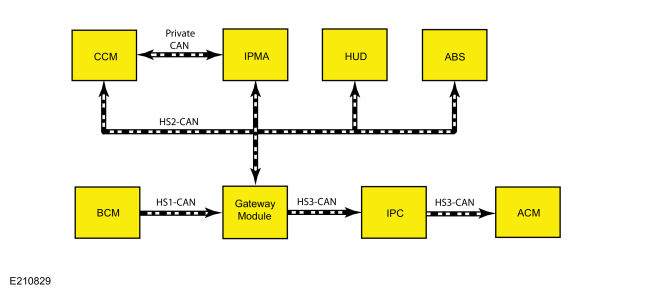
System Diagram
.jpg)
| Item | Description |
|---|---|
| 1 | ACM |
| 2 | HUD module |
| 3 | CCM |
| 4 | IPC |
| 5 | BCM |
| 6 | GWM |
| 7 | ABS module |
| 8 | IPMA |
Network Message Chart
Network Input Messages - ACM
| Broadcast Message | Originating Module | Message Purpose |
|---|---|---|
| Instrument panel cluster chime request | IPC | Data used to command a warning chime during a possible collision event and audio mute so that the warning chime can be heard. |
Network Input Messages - CCM
| Broadcast Message | Originating Module | Message Purpose |
|---|---|---|
| Collision avoidance and driver support camera status | IPMA | Data used to communicate the function status of the camera in the IPMA. |
| HUD status | HUD module | Data used for HUD module active and available status. |
| HUD fault | HUD module | Data used for HUD module fault status. |
Network Input Messages - HUD
| Broadcast Message | Originating Module | Message Purpose |
|---|---|---|
| HUD flash command | CCM | Flashes the HUD module LED array when commanded. |
| HUD flash rate | CCM | Flashes the HUD module LED array when commanded |
| Ignition status | BCM | Data used for ignition switch position input. |
Network Input Messages - IPC
| Broadcast Message | Originating Module | Message Purpose |
|---|---|---|
| Collision avoidance and driver support camera status | IPMA | Data used to command the pre-collision assist system fault status in the message center. |
| Collision avoidance and driver support chime request | CCM | Data used to command a warning chime that a collision event is possible. |
| Collision avoidance and driver support radar blocked warning | CCM | Data used to command a radar blocked message in the message center. |
| Forward collision chime request | CCM | Data used to command warning chime during possible collision event. When this message is received, the IPC sends the audio mute message to the ACM. |
| Forward collision warning message request | CCM | Data used to command warning chime and messages during possible collision event. |
| HUD fault | HUD module | Data used to command the forward collision warning system fault status message in the message center. |
Network Input Messages - IPMA
| Broadcast Message | Originating Module | Message Purpose |
|---|---|---|
| Collision avoidance and driver support radar status | CCM | Data used to communicate the function status of the radar in the CCM. |
Network Input Messages - ABS module
| Broadcast Message | Originating Module | Message Purpose |
|---|---|---|
| Collision mitigation by braking deceleration request | CCM | Data used to enable the brakes to slow vehicle speed when the pre-collision assist system determines that a collision is imminent. |
Pre-Collision Assist System Operation
The pre-collision assist system is an additional safety feature on vehicles equipped with adaptive cruise control. The system is active whether the adaptive cruise control system is on or off. If the system detects a vehicle, pedestrian or other object in the vehicle path of travel, the system provides three levels of functionality:
- Visual and audible alert
- Brake support
- Active braking
The system uses object detection information from the radar sensor integrated in the CCM and the forward-looking camera in the IPMA mounted in the interior rear view mirror. The CCM and the IPMA scan a designated area in front of the vehicle. Messages are sent between the CCM and the IPMA on dedicated CAN circuits, which determine whether an object, vehicle or pedestrian is in the path of travel, the approximate distance to the object and how fast the vehicle is approaching it.
When the vehicle approaches the object, the CCM sends a message to the HUD module on the HS-CAN2 to flash the red warning Light Emitting Diodes (LEDs). The CCM sends an alert message on the HS-CAN2 to the GWM, and then to the IPC on the HS-CAN3 to sound an audible alert and show a warning message in the message center display. The CCM also sends a message to the ABS module on the HS-CAN2 to pre-charge the brakes in order to prepare them for rapid braking by the driver. If the system determines that a collision is imminent, an active braking message is sent from the CCM to the ABS module. The system will reduce the gap between the brake pads and discs, applying the brakes to slow vehicle speed without driver intervention. The vehicle will stop the vehicle to help the driver avoid a collision or reduce damage caused by the impact.
The pre-collision alert system uses image recognition software that can differentiate between shapes, which allows the system to determine if the approaching object is a vehicle or a pedestrian. If the camera does not recognize the shape as the rear end of a vehicle or a pedestrian, the system will not provide full function. The system may not work properly at night, in direct or low sunlight, when camera vision is reduced due to weather conditions or due to a blocked CCM radar sensor. If the IPMA camera module is obstructed, the pre-collision system will not respond properly to pedestrians or stationary vehicles, and reduces the ability to recognize moving vehicles. Unconventional vehicle types, pedestrians in groups or with complex backgrounds, or partly obscured pedestrians also may not be properly detected by the system.
The pre-collision assist system is active at speeds above 5 km/h (3 mph) and pedestrian detection is active at speeds up to 80 km/h (50 mph).
The pre-collision assist system has three levels of sensitivity detection (HIGH, NORMAL and LOW) that can be changed through the message center display in the IPC. The alert sensitivity can be adjusted and active braking can be turned OFF in the IPC. The active braking function will revert back to ON at the next ignition cycle.
When a system fault is detected with the pre-collision assist system, the message PRE-COLLISION ASSIST NOT AVAILABLE, PRE-COLLISION ASSIST NOT AVAILABLE SENSOR BLOCKED, or PRE-COLLISION ASSIST MALFUNCTION is displayed in the IPC message center.
Component Description
CCM
The CCM contains a radar sensor unit that determines the distance and relative speed of the vehicle that is in the path of travel.
HUD
The HUD contains the red Light Emitting Diodes (LEDs) that warn the driver of a possible collision event when commanded by the CCM.
There are certain situations when the warning Light Emitting Diodes (LEDs) cannot be seen, such as strong sunlight or when wearing sunglasses. The HUD module has a temperature sensor circuit that is integral to the module that senses the temperature of the Light Emitting Diodes (LEDs) internal to the module. When a high passenger compartment temperature such as strong sunlight is sensed by the temperature sensor, the warning Light Emitting Diodes (LEDs) can be temporarily disengaged. If this occurs, only the audible warning chime is used.
Warnings may not appear if there is little distance to the vehicle ahead or abrupt steering wheel and pedal movements are made.
IPMA
The IPMA is integral to the interior rear view mirror. The IPMA contains a forward-looking camera with a designated line of sight in front of the moving vehicle. The camera can detect and differentiate between an approaching object, vehicle or pedestrian in the path of travel. This information is shared with the CCM on dedicated CAN circuits.
 Collision Warning and Collision Avoidance System - Overview. Description and Operation
Overview
The forward collision warning system alerts the driver of a collision risk with a red warning LED indicator bar (which is part of the HUD module) located above the instrument panel and an audible warning chime from the IPC...
 Collision Warning and Collision Avoidance System. Diagnosis and Testing
DTC Charts
Diagnostics in this manual assume a certain skill level and knowledge of Ford-specific diagnostic practices. REFER to: Diagnostic Methods (100-00 General Information, Description and Operation)...
Other information:
Ford Fusion 2013–2020 Service Manual: Engine Component View. Description and Operation
Upper Engine Item Part Number Description 1 67506750 Oil level indicator 2 12A36612A366 Ignition coil on plug (4 required) 3 9D3769D376 Fuel injection pump 4 9D3549D354 Fuel injection pump-to-fuel rail fuel supply tube 5 9H4879H487 Fuel rail 6 6C2876C287 Fuel injection pump tappet 7 9F5939F593 Fuel injector (4..
Ford Fusion 2013–2020 Service Manual: Hydraulic Control Unit (HCU). Removal and Installation
Removal NOTE: Removal steps in this procedure may contain installation details. NOTE: The HCU and ABS module are released individually. A new HCU does not come equipped with an ABS module. All vehicles Remove the battery tray. Refer to: Battery Tray (414-01 Battery, Mounting and Cables, Removal and Installation). Vehicles with manual transmission D..
Categories
- Manuals Home
- 2nd Generation Ford Fusion Owners Manual
- 2nd Generation Ford Fusion Service Manual
- Main Control Valve Body. Removal and Installation
- Intake Manifold. Removal and Installation
- Starter Motor. Removal and Installation
- New on site
- Most important about car
Adjusting the Steering Wheel
WARNING: Do not adjust the steering wheel when your vehicle is moving.
Note: Make sure that you are sitting in the correct position.