Ford Fusion: Anti-Lock Brake System (ABS) and Stability Control / Hydraulic Control Unit (HCU). Removal and Installation
Removal
NOTE: Removal steps in this procedure may contain installation details.
NOTE: The HCU and ABS module are released individually. A new HCU does not come equipped with an ABS module.
All vehicles
-
Remove the battery tray.
Refer to: Battery Tray (414-01 Battery, Mounting and Cables, Removal and Installation).
Vehicles with manual transmission
-
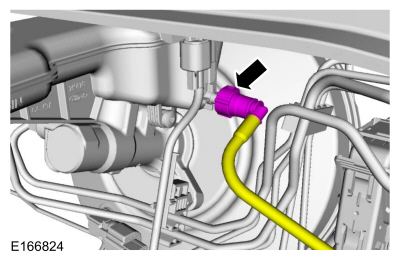
Disconnect the clutch master cylinder supply tube fitting.
 |
All vehicles
-
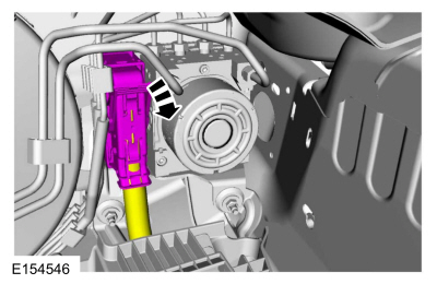
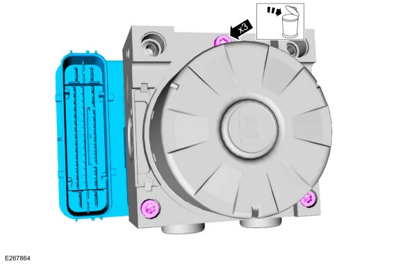
Disconnect the ABS module electrical connector.
 |
-
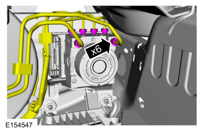
NOTICE: Make sure that all openings are sealed.
NOTICE: If the fluid is spilled on the paintwork, the affected area must be immediately washed down with cold water.
Disconnect the brake tube fittings.
Torque: 159 lb.in (18 Nm)
 |
-
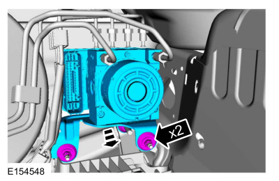
Remove the nuts and the HCU.
Torque: 80 lb.in (9 Nm)
 |
-
Remove the bolts and the HCU bracket.
Torque: 80 lb.in (9 Nm)
 |
-
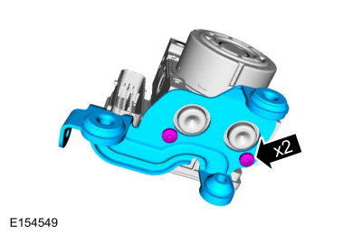
NOTICE: Make sure the HCU and ABS module are clean and free of brake fluid or foreign material before separating the components. Do not allow any brake fluid or foreign material to enter the mating side of the ABS module or component damage can occur.
Remove the screws and the ABS module. Discard the screws.
Torque: 49 lb.in (5.5 Nm)
 |
Installation
All vehicles
-
To install, reverse the removal procedure.
-
Bleed the brake system.
Refer to: Brake System Pressure Bleeding (206-00 Brake System - General Information, General Procedures).
-
If a new HCU
is being installed, carryout the IVD Initialization Sequence and Valve
Calibration using the scan tool and following the scan tool on-screen
instructions.
Vehicles with manual transmission
-
Bleed the clutch system.
 Front Wheel Speed Sensor. Removal and Installation
Removal
NOTE:
Removal steps in this procedure may contain installation details.
Remove the wheel and tire.
Refer to: Wheel and Tire (204-04A Wheels and Tires, Removal and Installation)...
 Rear Wheel Speed Sensor. Removal and Installation
Removal
NOTE:
Removal steps in this procedure may contain installation details.
All vehicles
With the vehicle in NEUTRAL, position it on a hoist...
Other information:
Ford Fusion 2013–2020 Service Manual: Battery Drain Check. General Procedures
Check NOTE: No factory-equipped vehicle should have more than a 25 mA (0.025 amp) – 50 mA (0.050) draw depending on the vehicle's accessories. Check for current drains on the battery in excess of 25 mA (0.025 amp) – 50 mA (0.050) with all the electrical accessories off and the vehicle at rest for at least 40 minutes...
Ford Fusion 2013–2020 Service Manual: Passive Anti-Theft System (PATS). Diagnosis and Testing
DTC Charts Diagnostics in this manual assume a certain skill level and knowledge of Ford-specific diagnostic practices. REFER to: Diagnostic Methods (100-00 General Information, Description and Operation). BCM DTC Chart DTC Description Action B10C7:01 Interior Trunk Antenna: General Electrical Failure ..
Categories
- Manuals Home
- 2nd Generation Ford Fusion Owners Manual
- 2nd Generation Ford Fusion Service Manual
- Front Controls Interface Module (FCIM). Removal and Installation
- Starter Motor. Removal and Installation
- Under Hood Overview - 1.5L EcoBoost™, 2.0L EcoBoost™, 2.5L, 2.7L EcoBoost™
- New on site
- Most important about car
Direction Indicators. Interior Lamps
Direction Indicators

Push the lever up or down to use the direction indicators.