Ford Fusion: Electronic Engine Controls - 1.5L EcoBoost (118kW/160PS) – I4 / Catalyst Monitor Sensor. Removal and Installation
Ford Fusion 2013–2020 Service Manual / Powertrain / Engine / Electronic Engine Controls - 1.5L EcoBoost (118kW/160PS) – I4 / Catalyst Monitor Sensor. Removal and Installation
Special Tool(s) / General Equipment
 |
303-476
(T94P-9472-A)
Socket, Exhaust Gas Oxygen Sensor TKIT-1994-LM/M TKIT-1994-F TKIT-1994-FLM/FM |
Materials
| Name | Specification |
|---|---|
| Motorcraft® High Temperature Nickel Anti-Seize Lubricant XL-2 |
- |
| Motorcraft® Penetrating and Lock Lubricant XL-1 |
- |
Removal
-
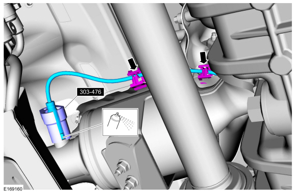
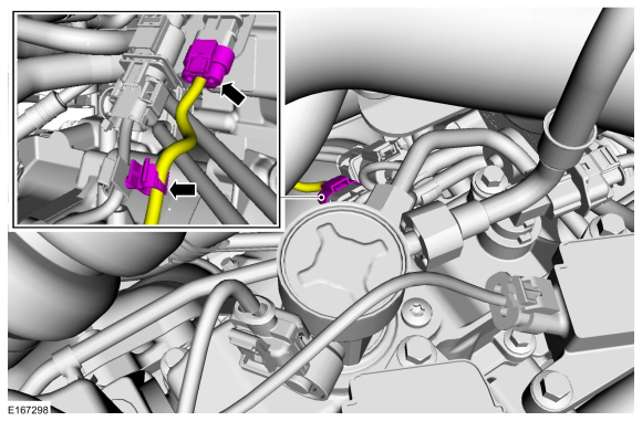
Disconnect the catalyst monitor sensor electrical connector and detach the wiring harness retainer.
 |
-
With the vehicle in N, position it on a hoist.
Refer to: Jacking and Lifting - Overview (100-02 Jacking and Lifting, Description and Operation).
-
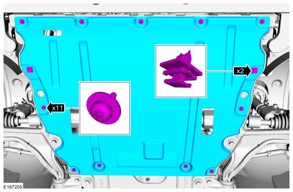
Remove the retainers and the engine undershield.
 |
-
Remove the catalyst monitor sensor and detach the wiring harness retainers.
Use Special Service Tool: 303-476 (T94P-9472-A) Socket, Exhaust Gas Oxygen Sensor.
Material: Motorcraft® Penetrating and Lock Lubricant / XL-1
 |
Installation
-
Calculate the correct torque wrench setting for the
following torque. Refer to Torque Wrench Adapter Formula in the Apex.
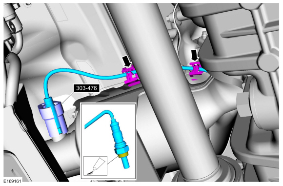
Install the catalyst monitor sensor and attach the wiring harness retainers.
Use Special Service Tool: 303-476 (T94P-9472-A) Socket, Exhaust Gas Oxygen Sensor.
Material: Motorcraft® High Temperature Nickel Anti-Seize Lubricant / XL-2
Torque: 35 lb.ft (48 Nm)
 |
-
Install the engine undershield and the retainers.
 |
-
Connect the catalyst monitor sensor electrical connector and attach the wiring harness retainer.
 |
 Camshaft Position (CMP) Sensor RH. Removal and Installation
Removal
NOTE:
Removal steps in this procedure may contain installation details.
Remove the engine appearance cover.
Disconnect the CMP sensor electrical connector, remove the retainer and the CMP sensor...
 Charge Air Cooler Coolant Temperature (CACCT) Sensor. Removal and Installation
Materials
Name
Specification
Motorcraft® Orange Prediluted Antifreeze/CoolantVC-3DIL-B
WSS-M97B44-D2
Removal
NOTE:
Removal steps in this procedure may contain installation details...
Other information:
Ford Fusion 2013–2020 Service Manual: Steering Wheel and Column Electrical Components. Diagnosis and Testing
DTC Charts BCM DTC Chart Diagnostics in this manual assume a certain skill level and knowledge of Ford-specific diagnostic practices. REFER to: Diagnostic Methods (100-00 General Information, Description and Operation). DTC Description Action B108A:01 Start Button: General Electrical Failure GO to Pinpoint Test..
Ford Fusion 2013–2020 Service Manual: Front Suspension Height Sensor. Removal and Installation
Removal NOTE: Removal steps in this procedure may contain installation details. With the vehicle in NEUTRAL, position it on a hoist. Refer to: Jacking and Lifting - Overview (100-02 Jacking and Lifting, Description and Operation). NOTE: RH height sensor assembly shown, LH similar. Disconnect the front suspension height sensor electrical connector. ..
Categories
- Manuals Home
- 2nd Generation Ford Fusion Owners Manual
- 2nd Generation Ford Fusion Service Manual
- Starter Motor. Removal and Installation
- Body Control Module (BCM). Removal and Installation
- Automatic Transmission Fluid Check - 1.5L EcoBoost™/2.0L EcoBoost™/2.5L. Automatic Transmission Fluid Check - 2.7L EcoBoost™
- New on site
- Most important about car
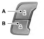
Power Door Locks
The power door lock control is on the driver and front passenger door panels.
Copyright © 2026 www.fofusion2.com