
Ford Fusion: Battery, Mounting and Cables / Battery. Diagnosis and Testing
Ford Fusion 2013–2020 Service Manual / Electrical / Battery and Charging System / Battery, Mounting and Cables / Battery. Diagnosis and Testing
General Equipment
| Diagnostic Battery Charger |
-
Use Ford approved battery test equipment.
-
Midtronics MDX-650 or P-300/P-600/490/1050
-
Midtronics GRX-3590 or 3000
-
Midtronics EXP-890
-
Midtronics MDX-650 or P-300/P-600/490/1050
Diagnostics in this manual assume a certain skill level and knowledge of Ford-specific diagnostic practices.
REFER to: Diagnostic Methods (100-00 General Information, Description and Operation).
 PINPOINT TEST A : BATTERY CONDITION TEST
 PINPOINT TEST A : BATTERY CONDITION TEST
|
Normal Operation and Fault Conditions Battery condition is determined by measuring battery terminal voltage after a specific discharge current is applied for a specified time period. Possible Sources
Visual Inspection and Pre-checks
|
||||
| A1 TEST THE BATTERY CONDITION | ||||
|
NOTE: Failure to fully charge the battery before retesting may cause false readings.
Is the battery OK?
|
 Battery and Cables - System Operation and Component Description. Description and Operation
System Operation
The battery is a 12V DC source connected in a negative ground system and is a voltage stabilizer for the 12V electrical system.
Component Description
Battery
Vehicles are equipped with a 12-volt, maintenance-free battery...
 Battery Charging. General Procedures
Charging
WARNING:
Before beginning any service procedure in this section,
refer to Safety Warnings in section 100-00 General Information. Failure
to follow this instruction may result in serious personal injury...
Other information:
Ford Fusion 2013–2020 Service Manual: Pinpoint Test - DTC: K. Diagnosis and Testing
B0072:11, B0072:12, B0072:13 and B0072:1A Refer to Wiring Diagrams Cell 46 for schematic and connector information. Normal Operation and Fault Conditions The RCM continuously monitors the passenger seatbelt anchor pretensioner circuits for the following faults: Resistance out of range Unexpected voltage Short to ground Faulted passenger seatbelt anchor pretens..
Ford Fusion 2013–2020 Service Manual: Engine Cooling - System Operation and Component Description. Description and Operation
System Operation Engine coolant flows primarily from the engine to the radiator circuit and back to the coolant pump. Coolant is sent from the coolant pump through the engine block and cylinder head. A separate circuit from the engine also feeds the heater core and turbocharger with coolant. The coolant pump, operated by engine rotation through the accessory drive belt, circulates the ..
Categories
- Manuals Home
- 2nd Generation Ford Fusion Owners Manual
- 2nd Generation Ford Fusion Service Manual
- Electrical
- Front Controls Interface Module (FCIM). Removal and Installation
- Powertrain
- New on site
- Most important about car
Cross Traffic Alert System Sensors
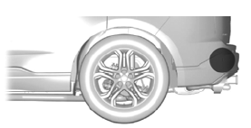
The sensors are behind the rear bumper on both sides of your vehicle.

Copyright © 2026 www.fofusion2.com