Ford Fusion: Power Brake Actuation / Brake Vacuum Pump - 1.5L EcoBoost (118kW/160PS) – I4. Removal and Installation
Materials
| Name | Specification |
|---|---|
| Motorcraft® Metal Surface Prep Wipes ZC-31-B |
- |
| Flange Sealant - Anaerobic Loctite® 51031 |
WSK-M2G348-A7 |
Removal
NOTE: Removal steps in this procedure may contain installation details.
-
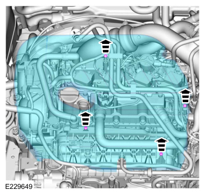
Remove the engine appearance cover.
 |
-
Remove the CAC intake pipe.
Refer to: Charge Air Cooler (CAC) Intake Pipe (303-12A Intake Air Distribution and Filtering - 1.5L EcoBoost (118kW/160PS) – I4, Removal and Installation).
-
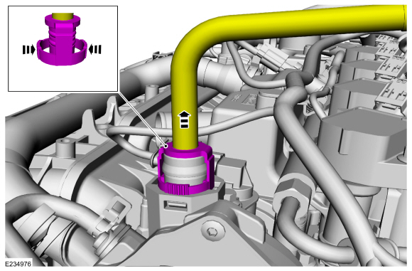
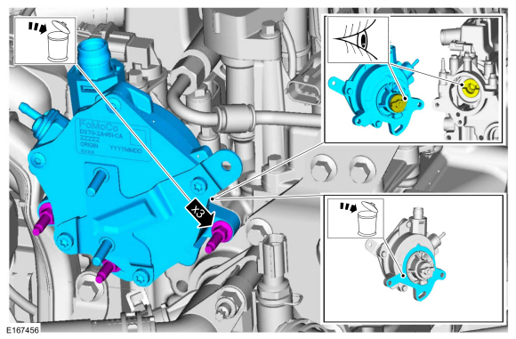
Squeeze the sides of the coupling and disconnect the vacuum tube.
 |
-
-
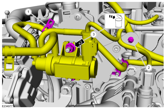
Release the clamp and disconnect the vacuum hose.
-
Detach the wiring and vacuum hose retainers.
-
Remove the nuts and position the vacuum control regulator aside. Discard the nuts.
Torque: 53 lb.in (6 Nm)
-
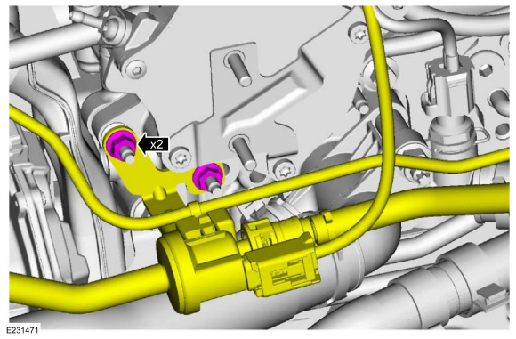
Release the clamp and disconnect the vacuum hose.
 |
-
Remove the nuts and position the EVAP purge valve and bracket aside.
Torque: 62 lb.in (7 Nm)
 |
-
NOTE: Manually align the brake vacuum pump drive key with the camshaft slot before installation.
-
Remove the bolts and the brake vacuum pump. Discard the bolts.
Torque: 89 lb.in (10 Nm)
-
Remove and discard the gasket.
-
Remove the bolts and the brake vacuum pump. Discard the bolts.
 |
-
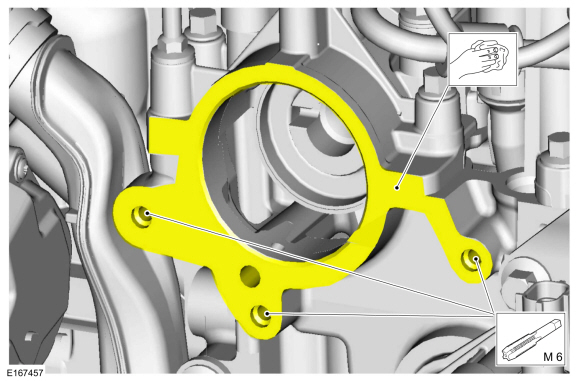
NOTE: Make sure the mating surfaces are clean and free of foreign material and thread lock residue is cleaned from the bolt holes.
Clean the mating surfaces and tap the bolt holes.
Material: Motorcraft® Metal Surface Prep Wipes / ZC-31-B
 |
Installation
-
NOTE: Make sure a new gasket is installed.
To install, reverse the removal procedure.
-
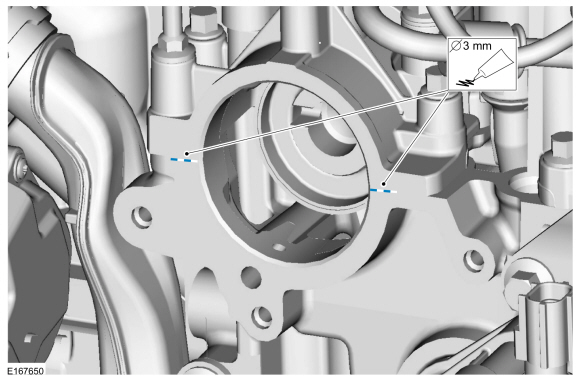
NOTE: If the brake vacuum pump is not secured within 10 minutes of sealant application, the sealant must be removed and the sealing area cleaned with metal surface prep. Failure to follow this procedure can cause future oil leakage.
Apply an 3mm bead of the specified sealant in the location shown.
Material: Flange Sealant - Anaerobic / Loctite® 51031 (WSK-M2G348-A7)
 |
 Brake Booster. Removal and Installation
Materials
Name
Specification
Motorcraft® MERCON® LV Automatic Transmission FluidXT-10-QLVC
WSS-M2C938-AMERCON® LV,
Removal
NOTE:
Removal steps in this procedure may contain installation details...
 Brake Vacuum Sensor. Removal and Installation
Removal
NOTE:
Removal steps in this procedure may contain installation details.
Remove the battery hold down bolt and plate.
Torque:
89 lb...
Other information:
Ford Fusion 2013–2020 Owners Manual: Smart Unlocks for Intelligent Access Keys
This feature helps to prevent you from locking your intelligent access key inside your vehicle’s passenger compartment or rear cargo area. When you electronically lock your vehicle with any door open, the transmission is in park (P) and the ignition is off, the system searches for an intelligent access key inside your vehicle after you close the last door...
Ford Fusion 2013–2020 Service Manual: Passenger Side Register. Removal and Installation
Special Tool(s) / General Equipment Interior Trim Remover Removal NOTE: Removal steps in this procedure may contain installation details. WARNING: Before beginning any service procedure in this section, refer to Safety Warnings in section 100-00 General Information...
Categories
- Manuals Home
- 2nd Generation Ford Fusion Owners Manual
- 2nd Generation Ford Fusion Service Manual
- Starter Motor. Removal and Installation
- Traction Control
- Memory Function
- New on site
- Most important about car
Fuel Quality
Choosing the Right Fuel
Your vehicle is designed to operate on regular unleaded gasoline with a minimum pump (R+M)/2 octane rating of 87.