Ford Fusion: Climate Control System - General Information / Air Conditioning (A/C) Compressor Outlet Line - 1.5L EcoBoost (118kW/160PS) – I4. Removal and Installation
Ford Fusion 2013–2020 Service Manual / Electrical / Climate Control System / Climate Control System - General Information / Air Conditioning (A/C) Compressor Outlet Line - 1.5L EcoBoost (118kW/160PS) – I4. Removal and Installation
Removal
NOTICE: During the removal or installation of components, cap, tape or otherwise appropriately protect all openings and tubes/fittings to prevent the ingress of dirt or other contamination. Remove caps, tape and other protective materials prior to installation.
NOTE: Removal steps in this procedure may contain installation details.
-
Recover the refrigerant. Refer to the appropriate Recovery procedure in Group 412.
-
With the vehicle in N, position it on a hoist.
Refer to: Jacking and Lifting - Overview (100-02 Jacking and Lifting, Description and Operation).
-
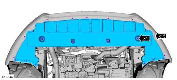
Remove the bolts and the radiator undershield.
 |
-
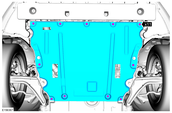
Remove the retainers and the engine undershield.
 |
-
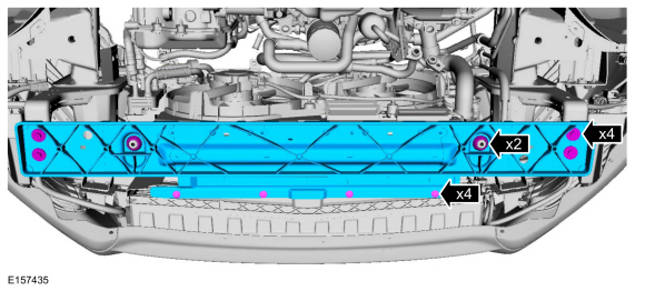
Remove the retainers, bolts, insulators and the cooling module support panel.
Torque: 18 lb.ft (24 Nm)
 |
-
NOTICE: Make sure that all openings are sealed.
-
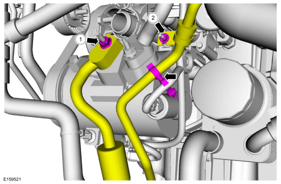
Remove the A/C compressor outlet line nut.
Torque: 133 lb.in (15 Nm)
-
Detach the wiring harness retainer, remove the nut and position the A/C compressor outet line aside. Discard the O-ring seal and gasket seal.
Torque: 18 lb.ft (25 Nm)
-
Make sure to cover any open ports to prevent debris from entering the system.
-
Remove the A/C compressor outlet line nut.
 |
-
Disconnect the A/C pressure transducer electrical connector, remove the bracket bolt and position aside the bracket.
Torque: 62 lb.in (7 Nm)
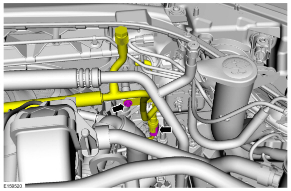 |
-
NOTICE: Make sure that all openings are sealed.
Remove the A/C compressor outlet line nut, disconnect the fitting and remove the A/C compressor outlet line. Discard the O-ring seal and gasket seal.
-
Make sure to cover any open ports to prevent debris from entering the system.
Torque: 133 lb.in (15 Nm)
-
Make sure to cover any open ports to prevent debris from entering the system.
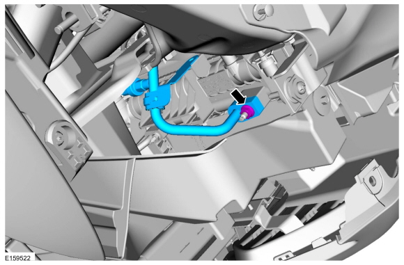 |
Installation
-
To install, reverse the removal procedure.
-
NOTICE: Only use the specified material to lubricate the seals.
Install and lubricate new O-ring seals. Refer to the appropriate Specifications in Group 412.
-
Lubricate the refrigerant system with the correct amount
of clean PAG oil. Refer to the appropriate Refrigerant Oil Adding
procedure in Group 412.
 Air Conditioning (A/C) Compressor Inlet Line - 1.5L EcoBoost (118kW/160PS) – I4. Removal and Installation
Removal
NOTICE:
During the removal or installation of components, cap, tape
or otherwise appropriately protect all openings and tubes/fittings to
prevent the ingress of dirt or other contamination...
 Air Conditioning (A/C) Pressure Transducer. Removal and Installation
Removal
NOTE:
Removal steps in this procedure may contain installation details .
WARNING:
Before beginning any service procedure in this
section, refer to Safety Warnings in section 100-00 General Information...
Other information:
Ford Fusion 2013–2020 Owners Manual: General Information. Keyless Starting
General Information WARNING: Extended idling at high engine speeds can produce very high temperatures in the engine and exhaust system, creating the risk of fire or other damage. WARNING: Do not park, idle or drive your vehicle on dry grass or other dry ground cover...
Ford Fusion 2013–2020 Service Manual: Evaporator Inlet and Outlet Manifold. Removal and Installation
Removal NOTICE: During the removal or installation of components, cap, tape or otherwise appropriately protect all openings and tubes/fittings to prevent the ingress of dirt or other contamination. Remove caps, tape and other protective materials prior to installation...
Categories
- Manuals Home
- 2nd Generation Ford Fusion Owners Manual
- 2nd Generation Ford Fusion Service Manual
- Steering Column Control Module (SCCM). Removal and Installation
- Body Control Module (BCM). Removal and Installation
- Main Control Valve Body. Removal and Installation
- New on site
- Most important about car
Direction Indicators. Interior Lamps
Direction Indicators
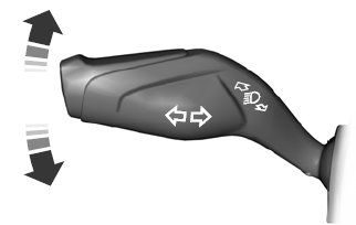
Push the lever up or down to use the direction indicators.
Copyright © 2025 www.fofusion2.com
