Ford Fusion: Climate Control System - General Information / Air Conditioning (A/C) Compressor Inlet Line - 1.5L EcoBoost (118kW/160PS) – I4. Removal and Installation
Ford Fusion 2013–2020 Service Manual / Electrical / Climate Control System / Climate Control System - General Information / Air Conditioning (A/C) Compressor Inlet Line - 1.5L EcoBoost (118kW/160PS) – I4. Removal and Installation
Removal
NOTICE: During the removal or installation of components, cap, tape or otherwise appropriately protect all openings and tubes/fittings to prevent the ingress of dirt or other contamination. Remove caps, tape and other protective materials prior to installation.
NOTE: Removal steps in this procedure may contain installation details.
-
Recover the refrigerant. Refer to the appropriate Recovery procedure in Group 412.
-
With the vehicle in N, position it on a hoist.
Refer to: Jacking and Lifting - Overview (100-02 Jacking and Lifting, Description and Operation).
-
Remove the retainers and the engine undershield.
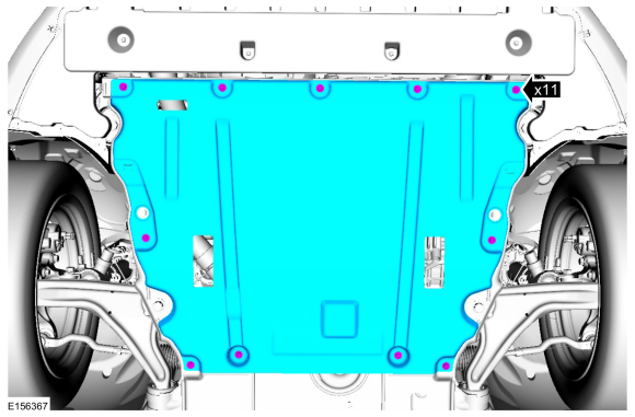 |
-
Remove the bolts and the radiator undershield.
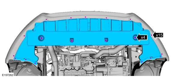 |
-
NOTICE: Make sure that all openings are sealed.
Remove the A/C compressor inlet line nut and disconnect the fitting. Discard the O-ring seal and gasket seal.
-
Make sure to cover any open ports to prevent debris from entering the system.
Torque: 133 lb.in (15 Nm)
-
Make sure to cover any open ports to prevent debris from entering the system.
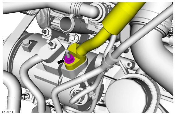 |
-
NOTICE: Make sure that all openings are sealed.
Remove the A/C compressor inlet line nut, disconnect the fitting and remove the A/C compressor inlet line. Discard the O-ring seal and gasket seal.
-
Make sure to cover any open ports to prevent debris from entering the system.
Torque: 133 lb.in (15 Nm)
-
Make sure to cover any open ports to prevent debris from entering the system.
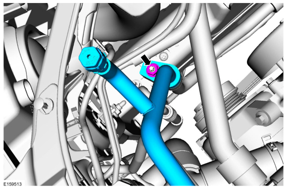 |
Installation
-
To install, reverse the removal procedure.
-
NOTICE: Only use the specified material to lubricate the seals.
Install and lubricate new O-ring seals. Refer to the appropriate Specifications in Group 412.
-
Lubricate the refrigerant system with the correct amount
of clean PAG oil. Refer to the appropriate Refrigerant Oil Adding
procedure in Group 412.
 Air Conditioning (A/C) Compressor Outlet Line - 1.5L EcoBoost (118kW/160PS) – I4. Removal and Installation
Removal
NOTICE:
During the removal or installation of components, cap, tape
or otherwise appropriately protect all openings and tubes/fittings to
prevent the ingress of dirt or other contamination...
Other information:
Ford Fusion 2013–2020 Service Manual: Pinpoint Test - DTC: N. Diagnosis and Testing
B0082:11, B0082:12, B0082:13 and B0082:1A Refer to Wiring Diagrams Cell 46 for schematic and connector information. Normal Operation and Fault Conditions The RCM continuously monitors the passenger seatbelt load limiter circuits for the following faults: Resistance out of range Unexpected voltage Short to ground Faulted passenger seatbelt load limiter If a faul..
Ford Fusion 2013–2020 Owners Manual: Fuel Filler Funnel Location. Running Out of Fuel
Fuel Filler Funnel Location The fuel filler funnel is under the luggage compartment floor covering. Running Out of Fuel Running out of fuel can cause damage not covered by the vehicle Warranty. If your vehicle runs out of fuel: Add a minimum of 1.3 gal (5 L) of fuel to restart the engine. You may need to switch the ignition from off to on several times after refueling to allow the fuel..
Categories
- Manuals Home
- 2nd Generation Ford Fusion Owners Manual
- 2nd Generation Ford Fusion Service Manual
- Automatic Transmission Fluid Check - 1.5L EcoBoost™/2.0L EcoBoost™/2.5L. Automatic Transmission Fluid Check - 2.7L EcoBoost™
- Memory Function
- Steering Column Control Module (SCCM). Removal and Installation
- New on site
- Most important about car
Manual Climate Control
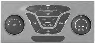
Note: Depending on your vehicle option package, the controls may look different from what you see here.
Copyright © 2025 www.fofusion2.com

