Ford Fusion: Vehicle Dynamic Suspension / Vehicle Dynamic Suspension - System Operation and Component Description. Description and Operation
System Operation
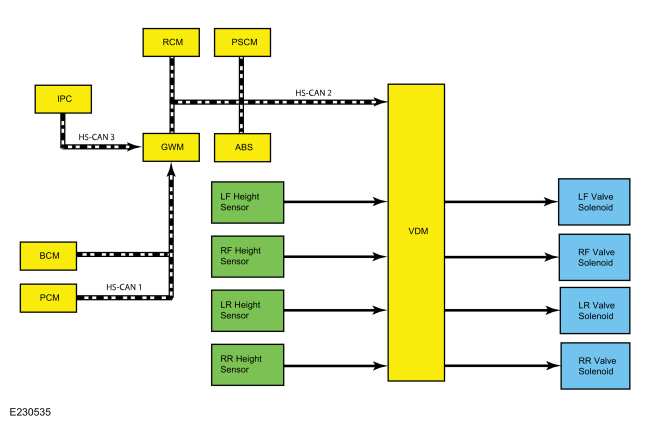
System Diagram
.jpg)
| Item | Description |
|---|---|
| 1 | VDM |
| 2 | LH front valve solenoid |
| 3 | PSCM |
| 4 | PCM |
| 5 | ABS module |
| 6 | LH front height sensor |
| 7 | RH front height sensor |
| 8 | LH rear height sensor |
| 9 | RH rear height sensor |
| 10 | BCM |
| 11 | RH front valve solenoid |
| 12 | LH rear valve solenoid |
| 13 | RH rear valve solenoid |
| 14 | IPC |
| 15 | RCM |
| 16 | GWM |
Network Message Chart
Module Network Input Messages - VDM
| Broadcast Message | Originating Module | Message Purpose |
|---|---|---|
| ABS active | ABS module | Indicates the current ABS activity, on or off. |
| Accelerator pedal position | PCM | This message is sent to the GWM and then to the VDM. Indicates the current accelerator pedal position. |
| Ambient air temperature | PCM | This message is sent to the GWM and then to the VDM. Indicates the current ambient air temperature. |
| Driven wheel torque request | PCM | This message is sent to the GWM and then to the VDM. Indicates the current amount of powertrain output requested by the PCM. |
| Engine RPM | PCM | This message is sent to the GWM and then to the VDM. Indicates the current engine speed in revolutions per minute. |
| Fuel level | IPC | This message is sent to the GWM and then to the VDM. Indicates the current vehicle fuel level as a percentage. |
| Gear lever position | PCM | This message is sent to the GWM and then to the VDM. Indicates the current transmission gear status. Used to determine the amount of dampening required during vehicle operation. |
| Ignition status | BCM | This message is sent to the GWM and then to the VDM. Indicates the current ignition status; off, accessory, run, start, invalid or unknown. |
| Life cycle mode | BCM | This message is sent to the GWM and then to the VDM. Indicates the current vehicle life cycle; normal, factory, not used or transport. |
| Message center display | IPC | This message is sent to the GWM and then to the VDM. Indicates if the vehicle is equipped with a message center and indicates the current status of the message center. |
| Message center feature configuration | IPC | This message is sent to the GWM and then to the VDM. Indicates if the vehicle is equipped with a message center configuration. |
| Odometer value | IPC | This message is sent to the GWM and then to the VDM. Indicates the current odometer value in kilometers. |
| Powertrain torque status | PCM | This message is sent to the GWM and then to the VDM. This message indicates the current status of the powertrain; power pack off torque not available, power pack on torque not available, start in progress torque not available and power pack on torque available. |
| Stability control brake active | ABS module | Indicates the current ESC activity, on or off. |
| Steering wheel angle sensor | PSCM | Indicates the current steering wheel angle relative to the straight ahead position and the number of complete 360 degree revolutions. |
| Traction control mode | ABS module | Indicates the current traction control activity, on or off. |
| Vehicle configuration data | BCM | This message is sent to the GWM and then to the VDM . Indicates the current vehicle configuration and optional equipment. |
| Vehicle lateral acceleration | ABS module | Indicates the current lateral acceleration as measured by the sensors in the RCM and relayed by the ABS module. |
| Vehicle lateral acceleration | RCM module | Indicates the current lateral acceleration as measured by the sensors in the RCM. |
| Vehicle longitudinal acceleration | ABS module | Indicates the current longitudinal acceleration as measured by the sensors in the RCM and relayed by the ABS module. |
| Vehicle longitudinal acceleration | RCM module | Indicates the current longitudinal acceleration as measured by the sensors in the RCM. |
| Vehicle roll rate | ABS module | Indicates the current roll rate as measured by the sensors in the RCM and relayed by the ABS module. |
| Vehicle roll rate | RCM module | Indicates the current roll rate as measured by the sensors in the RCM. |
| Vehicle speed | PCM | This message is sent to the GWM and then to the VDM. Indicates the current vehicle speed in kilometers per hour. |
| Vehicle yaw rate | ABS module | Indicates the current yaw rate as measured by the sensors in the RCM and relayed by the ABS module. |
| Vehicle yaw rate | RCM module | Indicates the current yaw rate as measured by the sensors in the RCM. |
Vehicle Dynamic Suspension
The VDM is connected to the HS-CAN to communicate with the ABS module, the PCM and other modules. With the information received the VDM monitors the heave, roll, pitch, cornering, braking and acceleration of the vehicle. Based on this information the VDM calculates the best action for each valve solenoid.
Once the valve solenoid is energized, the damping increases with the PWM duty cycle. At minimum current the damping is less than when max current is applied. The damper and valve solenoid have been designed so failure leads to a firm ride. The fail-safe level of damping is at a level equivalent to what is produced at higher currents, but it is not the same as the maximum current.
When the VDM is initialized (ignition ON), it carries out a preliminary electrical check of the height sensors, height sensor circuits, valve solenoids and valve solenoid circuits. Any malfunction detected in the system causes the VDM to set a DTC (diagnostic trouble code) and send a message over the HS-CAN2 to the GWM . The GWM then sends a message to the IPC over the HS-CAN3 and the IPC responds by displaying a message in the message center.
Component Description
Height Sensor
The height sensor uses a potentiometer to send a variable amount of voltage back to the VDM. The sensor has 3 circuits, one circuit is for the 5 volt sensor supply, one circuit is for sensor ground and one circuit is for the sensor output.
Valve Solenoid
The VDM uses a PWM output to control the valve solenoid. The solenoid opens or closes the valve depending on the amount of current supplied by the VDM. The higher the current, the more the valve is opened, resulting in a higher level of damping.
Vehicle Dynamics Control Module (VDM)
The VDM monitors all sensor inputs and all HS-CAN messages that relate to the vehicle dynamic suspension and then directly controls the valve solenoids. The VDM sends an individual electrical current to each valve solenoid to control the amount of damping required.
When one of the following components is installed new, disassembled, disconnected or removed the VDM requires calibration.
- VDM
- Suspension height sensor
- Front lower control arm
- Front strut assembly
- Rear lower control arm
- Rear shock
The calibration procedure is required for the system to learn the zero-position of the vehicle which means the vehicle must be on a level surface, must not be moving and cannot contain any passengers or cargo. The calibration procedure is carried out using a diagnostic scan tool. The calibration routine should not be performed with the vehicle raised off the ground or immediately after lowering the vehicle as the suspension will not be in a neutral position. The suspension must be neutralized before performing the calibration routine by driving the vehicle for a short distance such as around a parking lot.
 Vehicle Dynamic Suspension - Overview. Description and Operation
Overview
The
semi-active suspension dampening provides improved handling, comfort
and stability by continuously adjusting the adaptive shock absorber
force to the current road and driving conditions...
 Vehicle Dynamic Suspension. Diagnosis and Testing
DTC Chart
VDM
DTC Chart
Diagnostics in this manual assume a certain skill level and knowledge of Ford-specific diagnostic practices. REFER to: Diagnostic Methods (100-00 General Information, Description and Operation)...
Other information:
Ford Fusion 2013–2020 Service Manual: SYNC Module [APIM] to Universal Serial Bus (USB) Port Cable. Removal and Installation
Special Tool(s) / General Equipment Interior Trim Remover Removal NOTE: Removal steps in this procedure may contain installation details. Instrument panel cable Remove the FDIM. Refer to: Front Display Interface Module (FDIM) (415-00 Information and Entertainment System - General Information - Vehicles With: SYNC 3, Removal and Installation)...
Ford Fusion 2013–2020 Service Manual: Rear Driveshaft. Removal and Installation
Special Tool(s) / General Equipment Flat-Bladed Screwdriver Punch Copper Hammer Removal NOTE: The max articulation of any CV is 10 degrees. The max articulation of any U-joint is 12 degrees. If the CV or any U-joint of the driveshaft is articulated further then the max allowable degrees damage may occur...
Categories
- Manuals Home
- 2nd Generation Ford Fusion Owners Manual
- 2nd Generation Ford Fusion Service Manual
- Garage Door Opener
- Cylinder Head. Removal and Installation
- Body Control Module (BCM). Removal and Installation
- New on site
- Most important about car
Direction Indicators. Interior Lamps
Direction Indicators

Push the lever up or down to use the direction indicators.