Ford Fusion: Fuel Charging and Controls - Turbocharger - 1.5L EcoBoost (118kW/160PS) – I4 / Turbocharger. Removal and Installation
Special Tool(s) /
General Equipment
| Hose Clamp Remover/Installer |
Materials
| Name |
Specification |
Motorcraft® Metal Brake Parts Cleaner
PM-4-A, PM-4-B |
-
|
Removal
NOTICE:
The turbocharger compressor vanes can be damaged by even the
smallest particles. When removing any turbocharger or engine air intake
system component, ensure that no debris enters the system. Failure to
do so may result in damage to the turbocharger.
NOTE:
Removal steps in this procedure may contain installation details.
-
Remove the air cleaner outlet pipe.
Refer to: Air Cleaner Outlet Pipe (303-12A Intake Air Distribution and Filtering - 1.5L EcoBoost (118kW/160PS) – I4, Removal and Installation).
-
Remove the air cleaner.
Refer to: Air Cleaner (303-12A Intake Air Distribution and Filtering - 1.5L EcoBoost (118kW/160PS) – I4, Removal and Installation).
-
-
Remove the CAC intake pipe retaining bolt.
Torque:
71 lb.in (8 Nm)
-
Loosen the CAC intake pipe clamp , then disconnect the CAC intake pipe.
-
Loosen the TC bypass hose clamp , then disconnect the TC bypass hose.
-
Disconnect the TC bypass solenoid valve and IAT sensor electrical connectors.
-
Detach the wiring harness retainers.
-
-
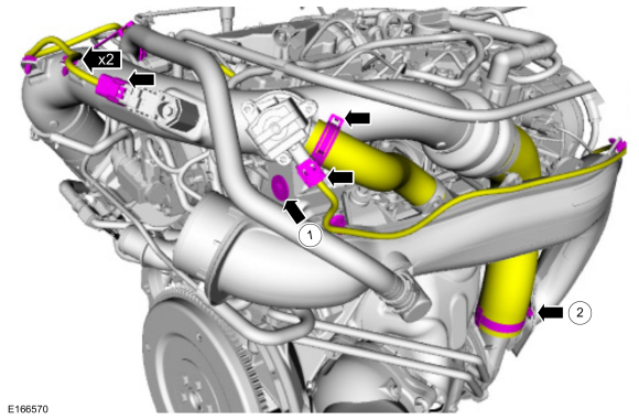
Loosen the TC air outlet pipe clamp.
Torque:
44 lb.in (5 Nm)
-
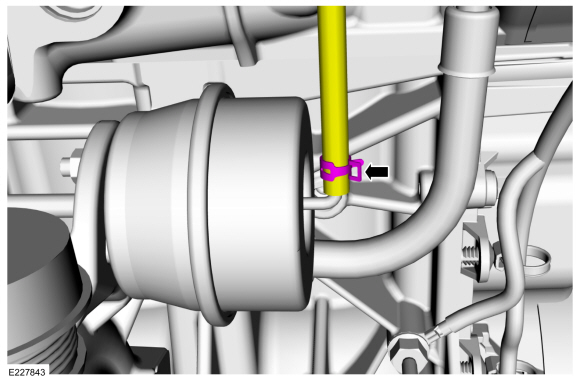
2. Squeeze the sides of the coupling and disconnect the vacuum tube.
-
Disconnect the crankcase ventilation tube quick release coupling.
Refer to: Quick Release Coupling (310-00A Fuel System - General Information - 1.5L EcoBoost (118kW/160PS) – I4, General Procedures).
-
Disconnect the IAT2 sensor electrical connector and remove the TC air outlet pipe.
-
-
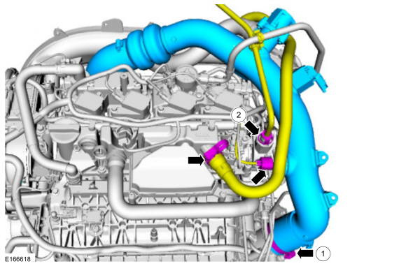
Loosen the TC air inlet pipe clamp.
Torque:
44 lb.in (5 Nm)
-
2. Remove the TC air inlet pipe retaining bolts.
-
Detach the wiring harness retainers and remove the TC air inlet pipe.
Torque:
71 lb.in (8 Nm)
-
Remove the catalytic converter.
Refer to: Catalytic Converter (309-00A Exhaust System - 1.5L EcoBoost (118kW/160PS) – I4, Removal and Installation).
-
Drain the cooling system.
Refer to: Engine Cooling System Draining, Vacuum Filling and Bleeding (303-03A Engine Cooling - 1.5L EcoBoost (118kW/160PS) – I4, General Procedures).
-
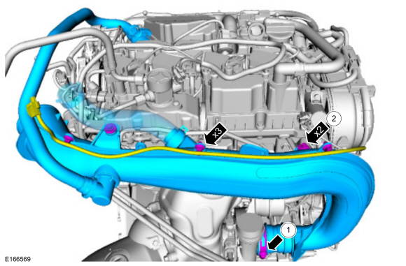
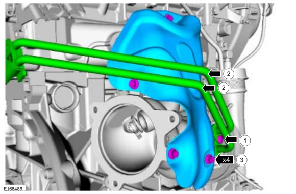
-
Disconnect the TC coolant hose clamps and position the TC coolant hoses aside.
-
Remove the TC coolant tube bracket bolt.
Torque:
97 lb.in (11 Nm)
-
Remove the TC coolant tube bracket bolt.
Torque:
17 lb.ft (23 Nm)
-
-
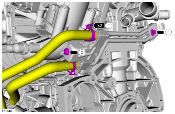
NOTE:
Note the TC coolant tube locations for installation.
Disconnect the TC coolant tube bolt from the TC.
Torque:
89 lb.in (10 Nm)
-
Remove the TC coolant tubes.
Material: Motorcraft® Metal Brake Parts Cleaner
/ PM-4-A, PM-4-B
-
Remove the TC heat shield bolts, then remove the TC heat shield.
Torque:
89 lb.in (10 Nm)
-
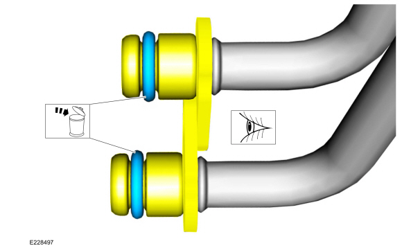
-
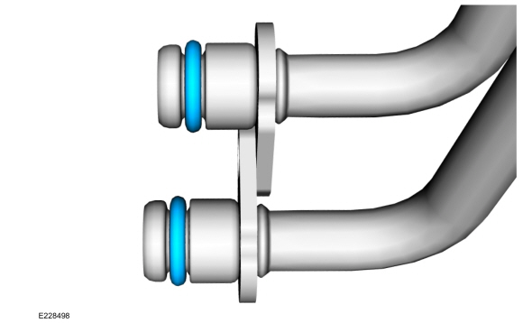
Remove and discard the TC coolant tube O-ring seals.
Material: Motorcraft® Metal Brake Parts Cleaner
/ PM-4-A, PM-4-B
-
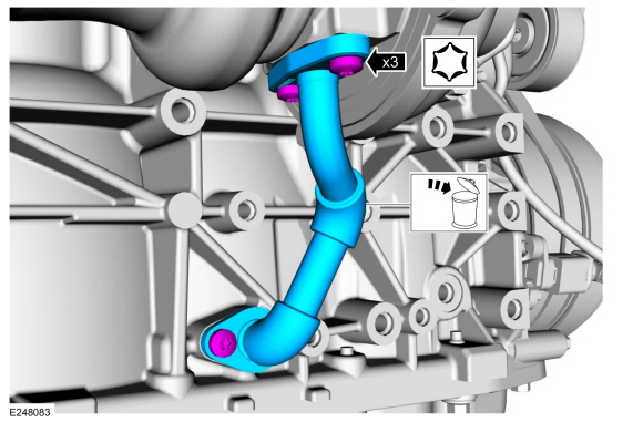
-
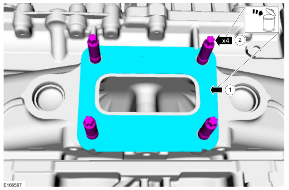
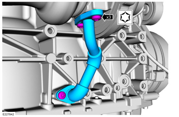
Remove the TC oil return tube to TC bolts.
-
Remove the TC oil return tube to engine block bolt, then remove and discard the TC oil return tube.
-
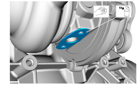
Remove and discard the TC oil return tube gasket. Clean the sealing surface.
-
Disconnect the TC wastegate control hose.
Use the General Equipment: Hose Clamp Remover/Installer
-
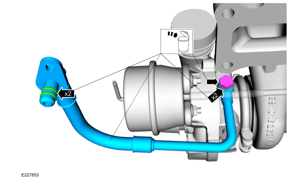
Remove the TC oil supply tube bolt , then disconnect the TC oil supply tube.
-
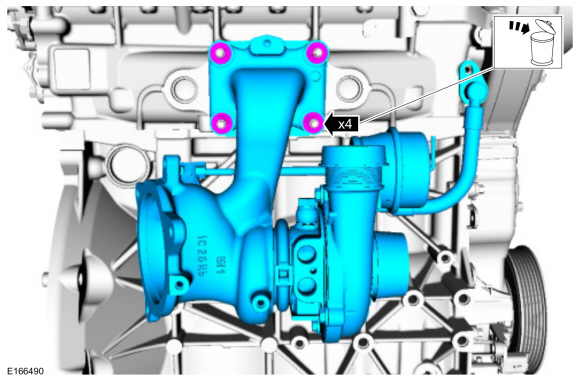
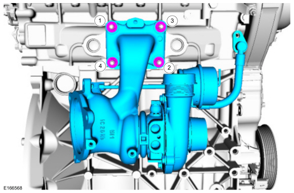
Remove and discard the TC mounting nuts. Remove the TC.
-
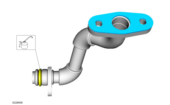
Remove the and discard the TC oil supply tube assembly, including the bolt, the sealing washers and the O-rings seals.
Installation
NOTICE:
Make sure that the mating faces are clean and free of foreign material.
-
NOTICE:
Do-not use a metal brush; damage to sealing area will result in leaks.
-
Carefully use a nylon brush to remove the old O-ring
residue and use brake cleaner to rinse the O-ring residue out of the
turbocharger O-ring bore. Inspect the area for deep scratches and
gouges.
-
Install the new TC
oil supply tube assembly, including the new bolt, the new sealing
washers and the new O-ring seals. Lubricate the new O-ring seals with
clean engine oil.
Material: Motorcraft® Metal Brake Parts Cleaner
/ PM-4-A, PM-4-B
Torque:
19 lb.ft (26 Nm)
-
Replace the TC mounting studs and the gasket.
Torque:
89 lb.in (10 Nm)
-
Install the TC and tighten the TC mounting nuts in the sequence shown.
Torque:
Stage 1:
Tighten in the sequence shown to: :
62 lb.in (7 Nm)
Stage 2:
Tighten in the sequence shown to: :
124 lb.in (14 Nm)
Stage 3:
Tighten in the sequence shown to: :
17 lb.ft (23 Nm)
-
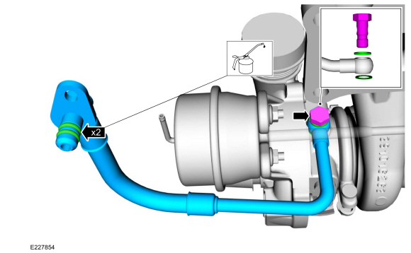
NOTICE:
When installing the oil supply tube, the spigot on
the oil supply tube must be fully engaged to the cylinder head with both
O-rings inserted before the fastener is tightened.
Install the TC oil supply tube, then install and tighten the TC oil supply tube bolt.
Torque:
89 lb.in (10 Nm)
-
Connect the TC wastegate control hose.
Use the General Equipment: Hose Clamp Remover/Installer
-
Install the new TC oil return tube gasket. Lubricate the O-ring seal with clean engine oil.
-
NOTICE:
Do-not use a metal brush; damage to sealing area will result in leaks.
-
Carefully use a nylon brush to remove the old O-ring
residue and use brake cleaner to rinse the O-ring residue out of the
turbocharger tube to engine O-ring bore. Inspect the area for deep
scratches and gouges.
-
Install the new turbocharger oil return tube, then
install and tighten the turbocharger oil return tube bolts.
Material: Motorcraft® Metal Brake Parts Cleaner
/ PM-4-A, PM-4-B
Torque:
89 lb.in (10 Nm)
-
Install the new the turbocharger coolant tube O-ring seals, then lubricate with clean engine coolant.
-
To install, reverse the removal procedure.
System Operation
Refer to Powertrain Control/Emissions Diagnosis (PC/ED) manual. See Section 1 Description and Operation.
Component Description
Refer to Powertrain Control/Emissions Diagnosis (PC/ED) manual...
Removal
NOTICE:
Whenever turbocharger air intake system components are
removed, always cover open ports to protect from debris. It is important
that no foreign material enter the system...
Other information:
Symptom Chart(s)
Symptom Chart: Symptom Chart - Exhaust System
Verify
the customer concern. Inspect the components of the exhaust system for
obvious signs of damage or other mechanical concerns using the following
chart.
Visual Inspection Chart - Mechanical
Mechanical
Exhaust pipe pinched or crushed
Damaged muffler
Broken or damaged..
Removal
NOTE:
LH side shown, RH side similar.
NOTE:
Removal steps in this procedure may contain installation details.
Remove the front door window regulator.
Refer to: Front Door Window Regulator (501-11 Glass, Frames and Mechanisms, Removal and Installation).
Remove the exterior front door handle.
Refer to: Exterior Front Door Handle (501-14 Handles, Locks, Latche..


 Turbocharger - System Operation and Component Description. Description and Operation
 Wastegate Control Valve Solenoid. Removal and Installation
 Press the button once to search
for a parking space.
Press the button once to search
for a parking space.