Ford Fusion: General Information / Wire Terminal Inspection and Removal. General Procedures
Disconnect
-
Refer to: Health and Safety Precautions (100-00 General Information, Description and Operation). WARNING:
Before beginning any service procedure in this
section, refer to Health and Safety Precautions in section 100-00
General Information. Failure to follow this instruction may result in
serious personal injury.
WARNING:
Before beginning any service procedure in this
section, refer to Health and Safety Precautions in section 100-00
General Information. Failure to follow this instruction may result in
serious personal injury.
NOTE: To avoid wiring pin (terminal) damage, Rotunda Flex Probes NUD105-R025D or Terminal Probe Kit 29-011A must be used to connect test equipment or jumper wires to pins (terminals).
- Male to female pin (terminal) fit is critical for correct connection and durability.
- Pin (terminal) fit may be checked by using the mating pin (terminal) to test for normal separation force (a damaged pin or terminal will have very low separation force from the mating pin or terminal).
- Correctly checking the separation force of small pins (terminals) may require removal of the connector terminal guide/retainer if it adds drag to the pin (terminal) insertion or removal.
- For more detail on the replacement of damaged connectors or pins (terminals) refer to the video below.
Click here to view a video version of this procedure.

-
NOTE: The connector hard-shell information, which is measured in millimeters is the distance from the front face of the connector to the engagement point on the terminal release tang. Mark the listed distance on the terminal removal tool prior to removing the terminal.
NOTE: The dimensions of the connector hard-shell and the connector terminals release tang are listed above the corresponding graphics.
-
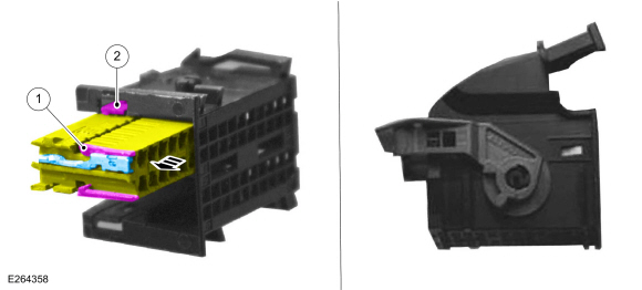
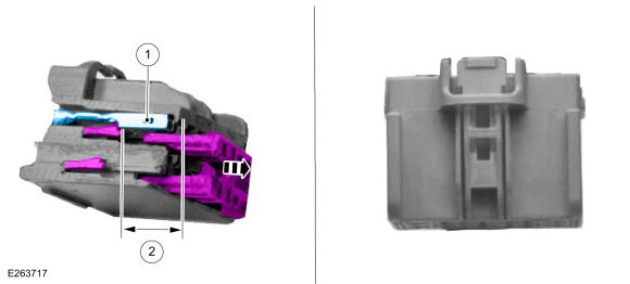
Audio Front Control Module (ACM), Body Control Module (BCM) and Instrument Panel Cluster (IPC) Electrical Connector
Callout Connector 1 External terminal release tang 2 Electrical connector locking tab
 |
-
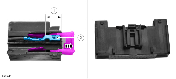
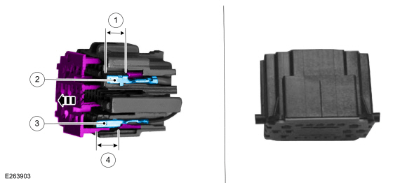
Audio Front Control Module (ACM), Front Controls Interface Module (FCIM), Gateway Module A (GWM), and Heating, Ventilation and Air Conditioning (HVAC) Control Module Electrical Connector
Callout Connector 1 Distance to release tang - 0.2953 in ( 7.5 mm) (inner terminal) - 0.4646 in ( 11.8 mm) (outer terminal) 2 Terminal width size - 0.0244 in ( .62 mm) (inner terminal) - 0.1102 in ( 2.8 mm) (outer terminal)
 |
-
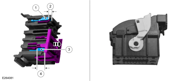
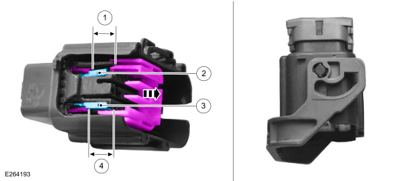
Body Control Module (BCM) Electrical Connector
Callout Connector 1 Terminal width size - 0.1102 in ( 2.8 mm) (inner terminal) - 0.2480 in ( 6.3 mm) (outer terminal) 2 Distance to release tang - 0.1260 in ( 3.2 mm) (inner terminal) - 0.1575 in ( 4 mm) (outer terminal) 3 Terminal width size - 0.0591 in ( 1.5 mm) 4 Distance to release tang - 0.3780 in ( 9.6 mm) (lower terminal)
 |
-
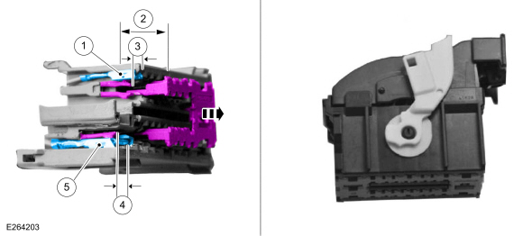
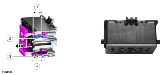
Body Control Module (BCM) Electrical Connector
Callout Connector 1 Terminal width size - 0.0591 in ( 1.5 mm) (inner terminal) - 0.1102 in ( 2.8 mm) (outer terminal) 2 Distance to release tang - 0.3780 in ( 9.6 mm) (inner terminal) 3 Distance to release tang - 0.1575 in ( 4 mm) 4 Distance to release tang - 0.1575 in ( 4 mm) 5 Terminal width size - 0.2480 in ( 6.3 mm)
 |
-
Body Harness In-line Electrical Connector
Callout Connector 1 Distance to release tang - 0.3346 in ( 8.5 mm) 2 Terminal width size - 0.1102 in ( 2.8 mm) 3 Terminal width size - 0.0591 in ( 1.5 mm) 4 Distance to release tang - 0.3858 in ( 9.8 mm) (inner)
 |
-
Body Harness In-line Electrical Connector
Callout Connector 1 Distance to release tang - 0.3543 in ( 9 mm) 2 Terminal width size - 0.0591 in ( 1.5 mm) (inner terminal) - 0.1102 in ( 2.8 mm) (outer terminal) 3 Terminal width size - 0.2480 in ( 6.3 mm) 4 Distance to release tang - 0.3543 in ( 9 mm)
 |
-
Body Harness In-line and Seat Harness Electrical Connector
Callout Connector 1 Distance to release tang - 0.4331 in ( 11 mm) 2 Terminal width size - 0.0591 in ( 1.5 mm) 3 Terminal width size - 0.0591 in ( 1.5 mm) 4 Distance to release tang - 0.4331 in ( 11 mm)
 |
-
Body Harness In-line and Seat Module Electrical Connector
Callout Connector 1 Terminal width size - 0.0591 in ( 1.5 mm) 2 Distance to release tang - 0.3937 in ( 10 mm)
 |
 Diagnostic Trouble Code Charts. Diagnosis and Testing
Master DTC Index
ABS Module
REFER to: Anti-Lock Brake System (ABS) and Stability Control (206-09 Anti-Lock Brake System (ABS) and Stability Control, Diagnosis and Testing)...

Other information:
Ford Fusion 2013–2020 Service Manual: Pinpoint Test - DTC: A. Diagnosis and Testing
B0001:11, B0001:12, B0001:13 and B0001:1A Refer to Wiring Diagrams Cell 46 for schematic and connector information. Normal Operation and Fault Conditions The RCM continuously monitors the driver airbag stage 1 circuits for the following faults: Resistance out of range Unexpected voltage Short to ground Faulted driver airbag If a fault is detected, the RCM..
Ford Fusion 2013–2020 Owners Manual: Perchlorate. Ford Credit. Replacement Parts Recommendation
Perchlorate Certain components in your vehicle such as airbag modules, seatbelt pretensioners and remote control batteries may contain perchlorate material. Special handling may apply for service or vehicle end of life disposal. For more information visit: Ford Credit US Only Ford Credit offers a full range of financing and lease plans to help you acquire your vehicle. If you have financed..
Categories
- Manuals Home
- 2nd Generation Ford Fusion Owners Manual
- 2nd Generation Ford Fusion Service Manual
- Load Carrying
- Main Control Valve Body. Removal and Installation
- Engine - 1.5L EcoBoost (118kW/160PS) – I4
- New on site
- Most important about car
Direction Indicators. Interior Lamps
Direction Indicators

Push the lever up or down to use the direction indicators.