 WARNING:
Do not handle, move or change the original horizontal
mounting position of the Restraints Control Module (RCM) while the
Restraints Control Module (RCM) is connected and the ignition switch is
ON. Failure to follow this instruction may result in the accidental
deployment of the Safety Canopy® and cause serious personal injury or
death.
WARNING:
Do not handle, move or change the original horizontal
mounting position of the Restraints Control Module (RCM) while the
Restraints Control Module (RCM) is connected and the ignition switch is
ON. Failure to follow this instruction may result in the accidental
deployment of the Safety Canopy® and cause serious personal injury or
death.
|
| NOTE:
Most faults are due to connector and/or wiring concerns.
Carry out a thorough inspection and verification before proceeding with
the pinpoint test.
|
| NOTE:
Only disconnect or reconnect SRS
components when instructed to do so within a pinpoint test step.
Failure to follow this instruction may result in incorrect diagnosis of
the SRS.
|
| NOTE:
Always make sure the correct SRS
component is being installed. Parts released for other vehicles may not
be compatible even if they appear physically similar. Check the part
number listed in the Ford parts catalog to make sure the correct
component is being installed. If an incorrect SRS component is installed, Diagnostic Trouble Codes (DTCs) may set.
|
| NOTE:
The SRS must be fully operational and free of faults before releasing the vehicle to the customer.
|
| A1 RETRIEVE RCM (RESTRAINTS CONTROL MODULE)
DIAGNOSTIC TROUBLE CODES (DTCS) |
-
 WARNING:
Before beginning any service procedure in this
section, refer to Safety Warnings in section 100-00 General Information.
Failure to follow this instruction may result in serious personal
injury.
WARNING:
Before beginning any service procedure in this
section, refer to Safety Warnings in section 100-00 General Information.
Failure to follow this instruction may result in serious personal
injury.
REFER to: Pyrotechnic Device Health and Safety Precautions (100-00 General Information, Description and Operation).
-
Using a diagnostic scan tool, perform RCM self-test.
Was DTC B0001:11, B0001:12, B0001:13 or B0001:1A retrieved on-demand during self-test?
| Yes |
This fault cannot be cleared until it is corrected and the DTC is no longer retrieved on-demand during self-test.
For DTC B0001:13 or B0001:1A, GO to A2
For DTC B0001:11, GO to A12
For DTC B0001:12, GO to A15
|
| No |
This is an intermittent fault when present as a CMDTC only.
For DTC B0001:13 or B0001:1A, GO to A20
For DTC B0001:11, GO to A21
For DTC B0001:12, GO to A22
|
|
| A2 CHECK THE DRIVER FRONTAL STAGE 1 DEPLOYMENT CONTROL RESISTANCE (DEPLOY_00_R) PID (PARAMETER IDENTIFICATION)
|
-
Using a diagnostic scan tool, view RCM Parameter Identifications (PIDs).
-
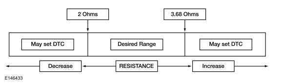
Monitor and record the resistance value displayed by the DEPLOY_00_R PID.
Does the PID value read between 2 and 3.68 ohms?
|
| A3 CHECK THE DRIVER FRONTAL STAGE 1 DEPLOYMENT CONTROL RESISTANCE (DEPLOY_00_R) PID (PARAMETER IDENTIFICATION)
WHILE CARRYING OUT THE HARNESS TEST |
-
Remove the steering column shrouds to access the clockspring connectors.
REFER to: Steering Column Shrouds (501-05 Interior Trim and Ornamentation, Removal and Installation).
-
While monitoring the DEPLOY_00_R PID,
carry out the harness test of the driver airbag circuits and accessible
connectors (including any inline connectors) by wiggling and flexing
the wire harness, connectors, tilting and rotating the steering wheel
frequently. Record the resistance value indicated by the PID.
Does the PID value read between 2 and 3.68 ohms while carrying out the harness test?
| Yes |
DEPOWER the SRS.
REFER to: Supplemental Restraint System (SRS) Depowering and Repowering (501-20B Supplemental Restraint System, General Procedures).
REPAIR the connector, terminals or wire harness or INSTALL a new clockspring as needed. REFER to: Clockspring (501-20B Supplemental Restraint System, Removal and Installation). Refer to Wiring Diagrams Cell 5 for schematic and connector information.
GO to A23
|
| No |
For PID value less than 2 ohms, GO to A4
For PID value greater than 3.68 ohms, GO to A8
|
|
| A4 CHECK THE DRIVER FRONTAL STAGE 1 DEPLOYMENT CONTROL DTC (DIAGNOSTIC TROUBLE CODE)
FOR A FAULT STATUS CHANGE (LOW RESISTANCE INDICATED) |
|
NOTE:
This pinpoint test step attempts to change the fault reported by the RCM by inducing a different fault condition. If the reported fault changes, this indicates the RCM is functioning correctly and is not the source of the fault.
-
Depower the SRS.
REFER to: Supplemental Restraint System (SRS) Depowering and Repowering (501-20B Supplemental Restraint System, General Procedures).
-
Remove the driver airbag.
REFER to: Driver Airbag (501-20B Supplemental Restraint System, Removal and Installation).
-
Repower the SRS. Do not prove out the SRS at this time.
REFER to: Supplemental Restraint System (SRS) Depowering and Repowering (501-20B Supplemental Restraint System, General Procedures).
-
Using a diagnostic scan tool, perform RCM self-test.
-
DIAGNOSTIC TIP: When viewing Diagnostic
Trouble Codes (DTCs) with the driver airbag disconnected, open circuit
faults are normally retrieved on stages 1 and 2.
Did the on-demand DTC change from B0001:1A to B0001:13?
|
| A5 CHECK THE DRIVER FRONTAL STAGE 1 DEPLOYMENT CONTROL DTC (DIAGNOSTIC TROUBLE CODE)
FOR A FAULT STATUS CHANGE (LOW RESISTANCE INDICATED) (CLOCKSPRING DISCONNECTED) |
|
NOTE:
This pinpoint test step attempts to change the fault reported by the RCM by inducing a different fault condition. If the reported fault changes, this indicates the RCM is functioning correctly and is not the source of the fault.
-
Depower the SRS.
REFER to: Supplemental Restraint System (SRS) Depowering and Repowering (501-20B Supplemental Restraint System, General Procedures).
-
Disconnect
SCCM
C218A
.
-
NOTE:
The clockspring connector is referred to as a SCCM connector. The clockspring is available for service separate from the SCCM.
Remove the steering column shrouds to access the clockspring connectors.
REFER to: Steering Column Shrouds (501-05 Interior Trim and Ornamentation, Removal and Installation).
-
Repower the SRS. Do not prove out the SRS at this time.
REFER to: Supplemental Restraint System (SRS) Depowering and Repowering (501-20B Supplemental Restraint System, General Procedures).
-
Using a diagnostic scan tool, perform RCM self-test.
-
DIAGNOSTIC TIP: When viewing Diagnostic
Trouble Codes (DTCs) with the clockspring disconnected, open circuit
faults are normally retrieved on stages 1 and 2.
Did the on-demand DTC change from B0001:1A to B0001:13?
|
| A6 CHECK FOR A SHORT BETWEEN DRIVER AIRBAG STAGE 1 CIRCUITS |
-
Measure:
Click to display connectors
|
Positive Lead
|
Measurement / Action
|
Negative Lead
|
|
C218A-11
|

|
C218A-12
|
Is the resistance greater than 10,000 ohms?
|
| A7 CHECK THE RCM (RESTRAINTS CONTROL MODULE)
FOR LOW RESISTANCE |
-
Depower the SRS.
REFER to: Supplemental Restraint System (SRS) Depowering and Repowering (501-20B Supplemental Restraint System, General Procedures).
-
Disconnect
RCM
C310A and C310B
.
-
Measure:
|
Positive Lead
|
Measurement / Action
|
Negative Lead
|
 C310A, pin 29, component side
|

|
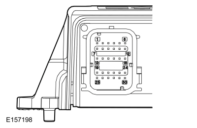 C310A, pin 30, component side
|
Is the resistance greater than 10,000 ohms?
| Yes |
REPAIR the driver airbag stage 1 circuit(s) for a short together.
Refer to Wiring Diagrams Cell 5 for schematic and connector information.
GO to A24
|
|
| A8 CHECK THE DRIVER AIRBAG STAGE 1 CIRCUITS FOR AN OPEN |
-
Depower the SRS.
REFER to: Supplemental Restraint System (SRS) Depowering and Repowering (501-20B Supplemental Restraint System, General Procedures).
-
Remove the driver airbag.
REFER to: Driver Airbag (501-20B Supplemental Restraint System, Removal and Installation).
-
Disconnect
RCM
C310A and C310B
.
-
Measure:
Click to display connectors
|
Positive Lead
|
Measurement / Action
|
Negative Lead
|
|
C310A-29
|

|
C216A-1
|
|
C310A-30
|

|
C216A-2
|
Are the resistances less than 1 ohm?
|
| A9 CHECK THE DRIVER AIRBAG STAGE 1 CIRCUITS FOR AN OPEN (CLOCKSPRING DISCONNECTED) |
-
Disconnect
SCCM
C218A
.
-
NOTE:
The clockspring connector is referred to as a SCCM connector. The clockspring is available for service separate from the SCCM.
Remove the steering column shrouds to access the clockspring connectors.
REFER to: Steering Column Shrouds (501-05 Interior Trim and Ornamentation, Removal and Installation).
-
Measure:
Click to display connectors
|
Positive Lead
|
Measurement / Action
|
Negative Lead
|
|
C310A-29
|

|
C218A-12
|
|
C310A-30
|

|
C218A-11
|
Are the resistances less than 0.5 ohm?
| No |
REPAIR the circuit(s).
Refer to Wiring Diagrams Cell 5 for schematic and connector information.
GO to A24
|
|
| A10 CHECK THE DRIVER AIRBAG STAGE 1 DEPLOYMENT CONTROL DTC (DIAGNOSTIC TROUBLE CODE)
FOR A FAULT STATUS CHANGE (OPEN INDICATED) |
|
NOTE:
This pinpoint test step attempts to change the fault reported by the RCM by inducing a different fault condition. If the reported fault changes, this indicates the RCM is functioning correctly and is not the source of the fault.
-
Connect
RCM
C310A and C310B
.
-
Connect a fused jumper wire:
Click to display connectors
|
Lead 1
|
Measurement / Action
|
Lead 2
|
|
C216A-1
|

|
C216A-2
|
-
Repower the SRS. Do not prove out the SRS at this time.
REFER to: Supplemental Restraint System (SRS) Depowering and Repowering (501-20B Supplemental Restraint System, General Procedures).
-
Using a diagnostic scan tool, perform RCM self-test.
-
DIAGNOSTIC TIP: When viewing Diagnostic
Trouble Codes (DTCs) with the driver airbag stage 1 circuits shorted
together, a low resistance fault is normally retrieved on stage 1. Stage
2 shows an open circuit fault because the driver airbag is
disconnected.
Was DTC B0001:1A retrieved on-demand during self-test?
| Yes |
REMOVE the fused jumper wire and GO to A17
|
| No |
REMOVE the fused jumper wire and GO to A11
|
|
| A11 CHECK THE DRIVER AIRBAG STAGE 1 DEPLOYMENT CONTROL DTC (DIAGNOSTIC TROUBLE CODE)
FOR A FAULT STATUS CHANGE (OPEN INDICATED) |
-
Depower the SRS.
REFER to: Supplemental Restraint System (SRS) Depowering and Repowering (501-20B Supplemental Restraint System, General Procedures).
-
Disconnect
SCCM
C218A
.
-
NOTE:
The clockspring connector is referred to as a SCCM connector. The clockspring is available for service separate from the SCCM.
Remove the steering column shrouds to access the clockspring connectors.
REFER to: Steering Column Shrouds (501-05 Interior Trim and Ornamentation, Removal and Installation).
-
Connect a fused jumper wire:
Click to display connectors
|
Lead 1
|
Measurement / Action
|
Lead 2
|
|
C218A-11
|

|
C218A-12
|
-
Repower the SRS. Do not prove out the SRS at this time.
REFER to: Supplemental Restraint System (SRS) Depowering and Repowering (501-20B Supplemental Restraint System, General Procedures).
-
Using a diagnostic scan tool, perform RCM self-test.
-
DIAGNOSTIC TIP: When viewing Diagnostic
Trouble Codes (DTCs) with the driver airbag stage 1 circuits shorted
together, a low resistance fault is normally retrieved on stage 1. Stage
2 shows an open circuit fault because the driver airbag is
disconnected.
Was DTC B0001:1A retrieved on-demand during self-test?
| Yes |
REMOVE the fused jumper wire and GO to A18
|
| No |
REMOVE the fused jumper wire and GO to A19
|
|
| A12 CHECK THE DRIVER FRONTAL STAGE 1 DEPLOYMENT CONTROL DTC (DIAGNOSTIC TROUBLE CODE)
FOR A FAULT STATUS CHANGE (SHORT TO GROUND INDICATED) |
|
NOTE:
This pinpoint test step attempts to change the fault reported by the RCM by inducing a different fault condition. If the reported fault changes, this indicates the RCM is functioning correctly and is not the source of the fault.
-
Depower the SRS.
REFER to: Supplemental Restraint System (SRS) Depowering and Repowering (501-20B Supplemental Restraint System, General Procedures).
-
Remove the driver airbag.
REFER to: Driver Airbag (501-20B Supplemental Restraint System, Removal and Installation).
-
Repower the SRS. Do not prove out the SRS at this time.
REFER to: Supplemental Restraint System (SRS) Depowering and Repowering (501-20B Supplemental Restraint System, General Procedures).
-
Using a diagnostic scan tool, perform RCM self-test.
-
DIAGNOSTIC TIP: When viewing Diagnostic
Trouble Codes (DTCs) with the driver airbag disconnected, open circuit
faults are normally retrieved on stages 1 and 2.
Did the on-demand DTC change from B0001:11 to B0001:13?
|
| A13 CHECK THE DRIVER FRONTAL STAGE 1 DEPLOYMENT CONTROL DTC (DIAGNOSTIC TROUBLE CODE)
FOR A FAULT STATUS CHANGE (SHORT TO GROUND INDICATED) (CLOCKSPRING DISCONNECTED) |
|
NOTE:
This pinpoint test step attempts to change the fault reported by the RCM by inducing a different fault condition. If the reported fault changes, this indicates the RCM is functioning correctly and is not the source of the fault.
-
Disconnect
SCCM
C218A
.
-
Remove the steering column shrouds to access the clockspring connectors.
REFER to: Steering Column Shrouds (501-05 Interior Trim and Ornamentation, Removal and Installation).
-
Using a diagnostic scan tool, perform RCM self-test.
-
DIAGNOSTIC TIP: When viewing Diagnostic
Trouble Codes (DTCs) with the clockspring disconnected, open circuit
faults are normally retrieved on stages 1 and 2.
Did the on-demand DTC change from B0001:11 to B0001:13?
|
| A14 CHECK THE DRIVER AIRBAG STAGE 1 CIRCUITS FOR A SHORT TO GROUND |
-
Depower the SRS.
REFER to: Supplemental Restraint System (SRS) Depowering and Repowering (501-20B Supplemental Restraint System, General Procedures).
-
Disconnect
RCM
C310A and C310B
.
-
Measure:
Click to display connectors
|
Positive Lead
|
Measurement / Action
|
Negative Lead
|
|
C218A-11
|

|
Ground
|
|
C218A-12
|

|
Ground
|
Are the resistances greater than 10,000 ohms?
| No |
Due to the shorting bar feature in the RCM electrical connector, the fault can exist in either circuit. Do not remove or defeat the shorting bar. REPAIR the circuit(s).
Refer to Wiring Diagrams Cell 5 for schematic and connector information.
GO to A24
|
|
| A15 CHECK THE DRIVER FRONTAL STAGE 1 DEPLOYMENT CONTROL DTC (DIAGNOSTIC TROUBLE CODE)
FOR A FAULT STATUS CHANGE (SHORT TO BATTERY INDICATED) (CLOCKSPRING DISCONNECTED) |
|
NOTE:
This pinpoint test step attempts to change the fault reported by the RCM by inducing a different fault condition. If the reported fault changes, this indicates the RCM is functioning correctly and is not the source of the fault.
-
Depower the SRS.
REFER to: Supplemental Restraint System (SRS) Depowering and Repowering (501-20B Supplemental Restraint System, General Procedures).
-
Remove the driver airbag.
REFER to: Driver Airbag (501-20B Supplemental Restraint System, Removal and Installation).
-
Disconnect
SCCM
C218A
.
-
NOTE:
The clockspring connector is referred to as a SASM connector. The clockspring is available for service separate from the SASM.
Remove the steering column shrouds to access the clockspring connectors.
REFER to: Steering Column Shrouds (501-05 Interior Trim and Ornamentation, Removal and Installation).
-
Repower the SRS. Do not prove out the SRS at this time.
REFER to: Supplemental Restraint System (SRS) Depowering and Repowering (501-20B Supplemental Restraint System, General Procedures).
-
Using a diagnostic scan tool, perform RCM self-test.
-
DIAGNOSTIC TIP: When viewing Diagnostic
Trouble Codes (DTCs) with the clockspring disconnected, open circuit
faults are normally retrieved on stages 1 and 2.
Did the on-demand DTC change from B0001:12 to B0001:13?
|
| A16 CHECK THE DRIVER AIRBAG STAGE 1 CIRCUITS FOR A SHORT TO VOLTAGE |
-
Depower the SRS.
REFER to: Supplemental Restraint System (SRS) Depowering and Repowering (501-20B Supplemental Restraint System, General Procedures).
-
Disconnect
RCM
C310A and C310B
.
-
Repower the SRS. Do not prove out the SRS at this time.
REFER to: Supplemental Restraint System (SRS) Depowering and Repowering (501-20B Supplemental Restraint System, General Procedures).
-
Measure:
Click to display connectors
|
Positive Lead
|
Measurement / Action
|
Negative Lead
|
|
C218A-11
|

|
Ground
|
|
C218A-12
|

|
Ground
|
Is any voltage present?
| Yes |
Due to the shorting bar feature in the RCM electrical connector, the fault can exist in either circuit. Do not remove or defeat the shorting bar. REPAIR the circuit(s).
Refer to Wiring Diagrams Cell 5 for schematic and connector information.
GO to A24
|
|
| A17 CONFIRM THE DRIVER AIRBAG FAULT |
|
NOTE:
Make sure all SRS components and the RCM
electrical connectors are connected before carrying out the self-test.
If not, Diagnostic Trouble Codes (DTCs) will be recorded.
-
Depower the SRS.
REFER to: Supplemental Restraint System (SRS) Depowering and Repowering (501-20B Supplemental Restraint System, General Procedures).
-
Install the driver airbag.
REFER to: Driver Airbag (501-20B Supplemental Restraint System, Removal and Installation).
-
Repower the SRS. Do not prove out the SRS at this time.
REFER to: Supplemental Restraint System (SRS) Depowering and Repowering (501-20B Supplemental Restraint System, General Procedures).
-
Using a diagnostic scan tool, perform RCM self-test.
Was the original DTC retrieved on-demand during self-test?
| Yes |
INSTALL a new driver airbag.
REFER to: Driver Airbag (501-20B Supplemental Restraint System, Removal and Installation).
GO to A24
|
| No |
In the process of diagnosing the fault, the fault
condition has become intermittent. Do not install any new SRS components at this time. Install SRS components only when directed to do so in the pinpoint test.
For DTC B0001:13 or B0001:1A, GO to A20
For DTC B0001:11, GO to A21
For DTC B0001:12, GO to A22
|
|
| A18 CONFIRM THE CLOCKSPRING FAULT |
|
NOTE:
Make sure all SRS components and the RCM
electrical connectors are connected before carrying out the self-test.
If not, Diagnostic Trouble Codes (DTCs) will be recorded.
-
Depower the SRS.
REFER to: Supplemental Restraint System (SRS) Depowering and Repowering (501-20B Supplemental Restraint System, General Procedures).
-
Prior to reconnecting any previously disconnected SRS component:
-
inspect connector(s) (including any inline
connectors) for pushed-out, loose or spread terminals and loose or
frayed wire connections at terminals.
-
inspect wire harness for any damaged, pinched, cut or pierced wires.
-
inspect RCM
C310A and C310B Connector Position Assurance (CPA) lever/lock for correct operation.
-
repair any concerns found.
Refer to Wiring Diagrams Cell 5 for schematic and connector information.
-
Install the driver airbag.
REFER to: Driver Airbag (501-20B Supplemental Restraint System, Removal and Installation).
-
Repower the SRS. Do not prove out the SRS at this time.
REFER to: Supplemental Restraint System (SRS) Depowering and Repowering (501-20B Supplemental Restraint System, General Procedures).
-
Using a diagnostic scan tool, perform RCM self-test.
Was the original DTC retrieved on-demand during self-test?
| Yes |
INSTALL a new clockspring.
REFER to: Clockspring (501-20B Supplemental Restraint System, Removal and Installation).
GO to A24
|
| No |
In the process of diagnosing the fault, the fault
condition has become intermittent. Do not install any new SRS components at this time. Install SRS components only when directed to do so in the pinpoint test.
For DTC B0001:13 or B0001:1A, GO to A20
For DTC B0001:11, GO to A21
For DTC B0001:12, GO to A22
|
|
| A19 CONFIRM THE RCM (RESTRAINTS CONTROL MODULE)
FAULT |
|
NOTE:
Make sure all SRS components and the RCM
electrical connectors are connected before carrying out the self-test.
If not, Diagnostic Trouble Codes (DTCs) will be recorded.
-
Depower the SRS.
REFER to: Supplemental Restraint System (SRS) Depowering and Repowering (501-20B Supplemental Restraint System, General Procedures).
-
Prior to reconnecting any previously disconnected SRS component:
-
inspect connector(s) (including any inline
connectors) for pushed-out, loose or spread terminals and loose or
frayed wire connections at terminals.
-
inspect wire harness for any damaged, pinched, cut or pierced wires.
-
inspect RCM
C310A and C310B Connector Position Assurance (CPA) lever/lock for correct operation.
-
repair any concerns found.
Refer to Wiring Diagrams Cell 5 for schematic and connector information.
-
If previously removed, install the driver airbag.
REFER to: Driver Airbag (501-20B Supplemental Restraint System, Removal and Installation).
-
Connect
SCCM
C218A (if previously disconnected).
-
Connect
RCM
C310A and C310B
.
-
Repower the SRS. Do not prove out the SRS at this time.
REFER to: Supplemental Restraint System (SRS) Depowering and Repowering (501-20B Supplemental Restraint System, General Procedures).
-
Using a diagnostic scan tool, perform RCM self-test.
Was the original DTC retrieved on-demand during self-test?
| Yes |
CHECK OASIS for any applicable Technical Service Bulletins (TSBs). If a TSB exists for this concern, DISCONTINUE this test and FOLLOW TSB instructions. If no Technical Service Bulletins (TSBs) address this concern, INSTALL a new RCM.
REFER to: Restraints Control Module (RCM) (501-20B Supplemental Restraint System, Removal and Installation).
GO to A24
|
| No |
In the process of diagnosing the fault, the fault
condition has become intermittent. Do not install any new SRS components at this time. Install SRS components only when directed to do so in the pinpoint test.
For DTC B0001:13 or B0001:1A, GO to A20
For DTC B0001:11, GO to A21
For DTC B0001:12, GO to A22
|
|
| A20 CHECK THE DRIVER FRONTAL STAGE 1 DEPLOYMENT CONTROL RESISTANCE (DEPLOY_00_R) PID (PARAMETER IDENTIFICATION)
FOR AN INTERMITTENT LOW RESISTANCE OR OPEN CIRCUIT FAULT |
-
Using a diagnostic scan tool, view RCM Parameter Identifications (PIDs).
-
Remove the steering column shrouds to access the clockspring connectors.
REFER to: Steering Column Shrouds (501-05 Interior Trim and Ornamentation, Removal and Installation).
-
While monitoring the DEPLOY_00_R PID,
attempt to recreate the fault by wiggling connectors (including any
inline connectors) and flexing the wire harness, tilting and rotating
the steering wheel frequently. Record the resistance value indicated by
the PID.
Does the PID value read between 2 and 3.68 ohms?
| Yes |
The fault is not present and cannot be recreated at this time. Do not install any new SRS components at this time. Install SRS components only when directed to do so in the pinpoint test. GO to A23
|
| No |
If the driver airbag PID indicates incorrect resistance only when the steering wheel is rotated, INSTALL a new clockspring.
REFER to: Clockspring (501-20B Supplemental Restraint System, Removal and Installation).
For all other faults, DEPOWER the SRS and REPAIR as necessary.
Refer to Wiring Diagrams Cell 5 for schematic and connector information.
GO to A24
|
|
| A21 CHECK THE DRIVER FRONTAL STAGE 1 DEPLOYMENT CONTROL CIRCUITS FOR AN INTERMITTENT SHORT TO GROUND FAULT |
-
Remove the steering column shrouds to access the clockspring connectors.
REFER to: Steering Column Shrouds (501-05 Interior Trim and Ornamentation, Removal and Installation).
-
Attempt to recreate the fault by wiggling connectors
(including any inline connectors) and flexing the wire harness, tilting
and rotating the steering wheel frequently.
-
Using a diagnostic scan tool, perform RCM self-test.
Was DTC B0001:11 retrieved on-demand during self-test?
| Yes |
DEPOWER the SRS and REPAIR as necessary.
Refer to Wiring Diagrams Cell 5 for schematic and connector information.
GO to A24
|
| No |
The fault is not present and cannot be recreated at this time. Do not install any new SRS components at this time. Install SRS components only when directed to do so in the pinpoint test. GO to A23
|
|
| A22 CHECK THE DRIVER FRONTAL STAGE 1 DEPLOYMENT CONTROL CIRCUITS FOR AN INTERMITTENT SHORT TO BATTERY FAULT |
-
Depower the SRS.
REFER to: Supplemental Restraint System (SRS) Depowering and Repowering (501-20B Supplemental Restraint System, General Procedures).
-
Remove the driver airbag.
REFER to: Driver Airbag (501-20B Supplemental Restraint System, Removal and Installation).
-
Repower the SRS. Do not prove out the SRS at this time.
REFER to: Supplemental Restraint System (SRS) Depowering and Repowering (501-20B Supplemental Restraint System, General Procedures).
-
Remove the steering column shrouds to access the clockspring connectors.
REFER to: Steering Column Shrouds (501-05 Interior Trim and Ornamentation, Removal and Installation).
-
Attempt to recreate the fault by wiggling connectors
(including any inline connectors) and flexing the wire harness, tilting
and rotating the steering wheel frequently.
-
Using a diagnostic scan tool, perform RCM self-test.
Was DTC B0001:12 retrieved on-demand during self-test?
| Yes |
DEPOWER the SRS and REPAIR as necessary.
Refer to Wiring Diagrams Cell 5 for schematic and connector information.
GO to A24
|
| No |
The fault is not present and cannot be recreated at this time. Do not install any new SRS components at this time. Install SRS components only when directed to do so in the pinpoint test. GO to A23
|
|
| A23 CHECK THE HARNESS AND CONNECTORS |
-
Depower the SRS.
REFER to: Supplemental Restraint System (SRS) Depowering and Repowering (501-20B Supplemental Restraint System, General Procedures).
-
Remove the driver airbag.
REFER to: Driver Airbag (501-20B Supplemental Restraint System, Removal and Installation).
-
inspect connector(s) (including any inline
connectors) for corrosion, loose or spread terminals and loose or frayed
wire connections at terminals.
-
inspect wire harness for any damage, pinched, cut or pierced wires.
-
Inspect RCM
C310A and C310B Connector Position Assurance (CPA) lever/lock for correct operation.
Were any concerns found?
| Yes |
REPAIR as necessary.
Refer to Wiring Diagrams Cell 5 for schematic and connector information.
GO to A24
|
| No |
The fault is not present and cannot be recreated at this time. Do not install any new SRS components at this time. Install SRS components only when directed to do so in the pinpoint test. GO to A24
|
|
| A24 CHECK FOR ADDITIONAL SRS (SUPPLEMENTAL RESTRAINT SYSTEM)
DIAGNOSTIC TROUBLE CODES (DTCS) |
|
 WARNING:
Turn the ignition OFF and wait one minute to deplete
the backup power supply. Failure to follow this instruction may result
in serious personal injury or death in the event of an accidental
deployment.
WARNING:
Turn the ignition OFF and wait one minute to deplete
the backup power supply. Failure to follow this instruction may result
in serious personal injury or death in the event of an accidental
deployment.
-
Reconnect all SRS components (if previously disconnected).
-
If previously directed to depower the SRS, repower the SRS. Do not prove out the SRS at this time.
REFER to: Supplemental Restraint System (SRS) Depowering and Repowering (501-20B Supplemental Restraint System, General Procedures).
-
NOTE:
When selecting Restraints from the Self Test menu, DTCs are retrieved from the RCM, OCSM and, if equipped, BECMB.
Using a diagnostic scan tool, perform Restraints self-test.
Are any RCM, OCSM and/or BECMB Diagnostic Trouble Codes (DTCs) retrieved on-demand during self-test?
| Yes |
Do not clear any Diagnostic Trouble Codes (DTCs)
until all Diagnostic Trouble Codes (DTCs) have been resolved.
REFER to: Airbag Supplemental Restraint System (SRS) (501-20B Supplemental Restraint System, Diagnosis and Testing).
|
| No |
The repair is complete. RETURN the vehicle to the customer.
|
|
 Airbag Supplemental Restraint System (SRS). Diagnosis and Testing
 Pinpoint Test - DTC: B. Diagnosis and Testing