Ford Fusion: Steering Column / Steering Column - System Operation and Component Description. Description and Operation
System Operation
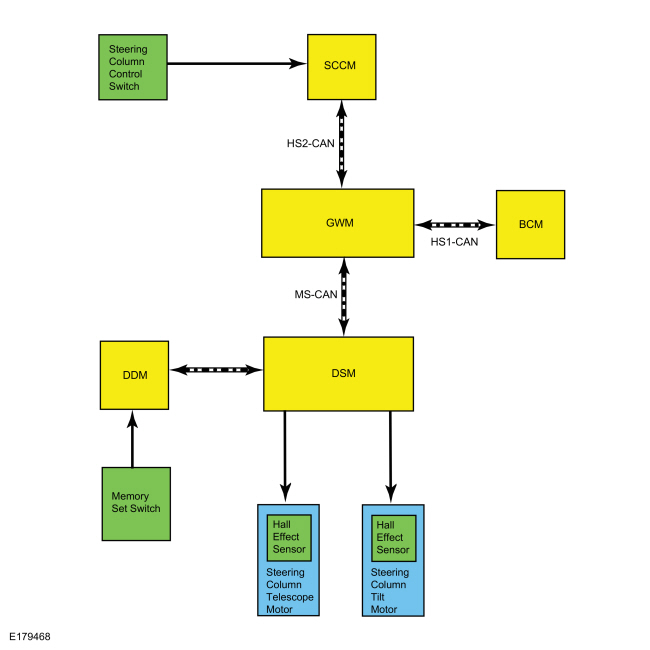
System Diagram
.jpg)
| Item | Description |
|---|---|
| 1 | Hall Effect Sensor |
| 2 | Steering Column Tilt Motor |
| 3 | DDM |
| 4 | SCCM |
| 5 | Memory Set Switch |
| 6 | DSM |
| 7 | BCM |
| 8 | MS-CAN |
| 9 | HS2-CAN |
| 10 | Steering Column Control Switch |
| 11 | Steering Column Telescope Motor |
| 12 | Hall Effect Sensor |
| 13 | GWM |
| 14 | HS1-CAN |
Network Message Chart
DSM Network Input Messages
| Broadcast Message | Originating Module | Message Purpose |
|---|---|---|
| Memory seat switch status | DDM | Used to recall memory set position when one of the memory set buttons are pressed. |
| Personality recall | BCM | Used to recall a memory set position when a key has been programmed to a memory set position and the unlock button on that key is pressed or the passive entry feature is used to enter the vehicle. |
| Steering column position switch status | SCCM | Used to control the adjustable steering column when the steering column control switch is pressed. |
Manual Adjustable Steering Column
The manual adjustable steering column is controlled by a mechanical lever on the underside of the steering column, which uses a cam to lock and unlock the steering column. The steering column can be adjusted when the lever is pulled downward. The steering column can be adjusted up or down and in or out. When the steering column is in the desired position(s), lifting the lever upward to its original position locks the steering column.
Power Adjustable Steering Column
The power adjustable steering column is mounted directly to and monitored by the SCCM. When the switch is pressed to move the column a direction, the SCCM sends a message to the DSM. The DSM provides the power and ground to the steering column tilt and telescoping motors to control the movement of the steering column.
Memory Column Operation
The memory SET switch is monitored by the DDM. When a memory position is recalled using the memory SET switch, the DDM sends a message to the DSM. The DSM activates the tilt/telescope motors to adjust the steering column to the position that is stored in the DSM memory. Once the steering column reaches the desired position, the DSM deactivates the steering column motors. If the DSM receives a steering column switch input during a memory position recall function, the module stops the memory recall and responds to the new steering column switch position input.
The DSM monitors the steering column position using Hall-effect sensors that are integral to the tilt and telescope motors. The sensors provide a signal used by the DSM to calculate the position of the steering column. The DSM uses this to store and recall memory positions, to activate the easy entry/easy exit feature and to make sure the tilt and telescope motors do not stall against the end of travel. If a tilt or telescope motor sensor DTC is set, the DSM does not recall programmed memory positions or activate the easy entry/easy exit feature.
The memory position recall is also used when a valid programmed key is associated with one of the memory SET buttons. When detected, the BCM sends a message to the DSM, which moves the steering column to the position that is stored in the DSM memory.
Easy Entry, Easy Exit
The easy entry/exit function moves the steering column to the full upward position when the vehicle is in PARK and the ignition is switched off.
The DSM records the current steering column position before powering the steering column for an easy exit operation. This recorded position returns the steering column to this position on the next easy entry operation. During easy entry operation, the steering column is either returned to the position previous to the easy exit operation or to the saved memory preset if a valid programmed key is used to enter the vehicle.
The DSM cancels this operation if a valid input is received from the steering column control switch or memory position switch.
The easy entry/exit feature can be activated or deactivated using the message center.
Jog Mode
If the DSM detects an invalid or no signal from either of the steering column tilt/telescope motor sensors, the affected steering column motor operates only in jog mode. Jog mode allows limited operation of the affected steering column motor only when using the steering column control switch. When the steering column control switch is operated during jog mode, the steering column moves in the desired direction for two seconds and then stops. The steering column control switch must be released, then pressed again in order to move the steering column for an additional second. Jog mode is an indication there is a tilt or telescoping motor sensor or circuit fault. If the adjustable steering column operates in jog mode, a DTC should be set in the DSM.
Component Description
Steering Column Control Switch
The steering column control switch is a momentary contact switch that is mounted directly to the left side of the SCCM and controls the forward, rearward, upward and downward movement of the steering column. The steering column control switch is serviced separately.
Steering Column Tilt Motor
The tilt motor controls the upward and downward position of the power adjustable steering column. The tilt motor is equipped with a Hall-effect type rotation sensor that sends signals to the DSM to calculate the up/down position of the steering column and to make sure the tilt motor does not stall against the steering column end of travel. The tilt motor is serviced separately from the steering column.
Steering Column Telescope Motor
The telescope motor controls the inward and outward position of the power adjustable steering column. The telescope motor is equipped with a Hall-effect type rotation sensor that sends signals to the DSM to calculate the forward/rearward position of the steering column and to make sure the telescope motor does not stall against the steering column end of travel. The telescope motor is not serviceable separately. If a new telescope motor is required, a new steering column must be installed.
DSM
The DSM controls the operation of the power steering column. The DSM communicates on the MS-CAN.
PMI is required when a new DSM is installed. The DSM hard stop/soft stops must be set/reset any time a new DSM, steering column tilt motor or steering column is replaced.
 Steering Column - Overview. Description and Operation
Steering Column Overview
The power adjustable steering column system consists of the following components:
Steering column
Upper and lower steering column shrouds
Telescopic and tilt motors
Steering column control switch
SCCM
DSM
The
steering column is the mechanical linkage between the steering wheel
and the steering gear...
 Steering Column. Diagnosis and Testing
DTC Charts
Diagnostics in this manual assume a certain skill level and knowledge of Ford-specific diagnostic practices. REFER to: Diagnostic Methods (100-00 General Information, Description and Operation)...
Other information:
Ford Fusion 2013–2020 Service Manual: Evaporative Emissions - System Operation and Component Description. Description and Operation
System Operation Refer to the PC/ED manual section 1 Description and Operation. System Diagram Item Description 1 Valve cover 2 Turbocharger inlet pipe 3 Air cleaner (ACL) outlet pipe 4 Vapor ejector 5 Turbocharger to CAC (Charge Air Cooler) tube 6 Dual check valve 7 EVAP (Evaporative Emission) canister pur..
Ford Fusion 2013–2020 Owners Manual: Adjusting the Headlamps
Vertical Aim Adjustment The headlamps on your vehicle are properly aimed at the assembly plant. If your vehicle has been in an accident, the alignment of your headlamps should be checked by your authorized dealer. Headlamp Aiming Target 8 feet (2.4 meters) Center height of lamp to ground 25 feet (7.6 meters) Horizontal reference line Vertical Aim Adjustment Procedure Park the vehicle ..
Categories
- Manuals Home
- 2nd Generation Ford Fusion Owners Manual
- 2nd Generation Ford Fusion Service Manual
- Powertrain
- Electrical
- Cylinder Head. Removal and Installation
- New on site
- Most important about car
Direction Indicators. Interior Lamps
Direction Indicators

Push the lever up or down to use the direction indicators.