Ford Fusion: Steering System / Steering Column
- Steering Column - Overview. Description and Operation
- Steering Column - System Operation and Component Description. Description and Operation
- Steering Column. Diagnosis and Testing
- Steering Wheel Cover Repair. General Procedures
- Steering Wheel. Removal and Installation
- Steering Column. Removal and Installation
- Steering Column Tilt Motor. Removal and Installation
 Tie Rod. Removal and Installation
Special Tool(s) /
General Equipment
Tie Rod End Remover
Tie Rod Remover and Installer
Boot Clamp Pliers
Materials
Name
Specification
Motorcraft® Premium Long-Life GreaseXG-1-E1
ESA-M1C75-B
Removal
NOTICE:
When servicing inner tie rods, install a new bellows boot
and clamps...
 Steering Column - Overview. Description and Operation
Steering Column Overview
The power adjustable steering column system consists of the following components:
Steering column
Upper and lower steering column shrouds
Telescopic and tilt motors
Steering column control switch
SCCM
DSM
The
steering column is the mechanical linkage between the steering wheel
and the steering gear...
Other information:
Ford Fusion 2013–2020 Service Manual: Pinpoint Test - DTC: M. Diagnosis and Testing
B007F:11, B007F:12, B007F:13 and B007F:1A Refer to Wiring Diagrams Cell 46 for schematic and connector information. Normal Operation and Fault Conditions The RCM continuously monitors the passenger seatbelt retractor pretensioner circuits for the following faults: Resistance out of range Unexpected voltage Short to ground Faulted passenger seatbelt retractor p..
Ford Fusion 2013–2020 Service Manual: Cylinder Block Core Plug Replacement. General Procedures
Special Tool(s) / General Equipment 100-001 (T50T-100-A) Slide Hammer Materials Name Specification Motorcraft® Threadlock 262TA-26 WSK-M2G351-A6 Repair All core plugs NOTE: Cylinder block core plug shown, cylinder head core plug similar. Using the Slide Hammer and a commercially available body dent puller attachment or commercially available ..
Categories
- Manuals Home
- 2nd Generation Ford Fusion Owners Manual
- 2nd Generation Ford Fusion Service Manual
- Garage Door Opener
- Intake Manifold. Removal and Installation
- Body Control Module (BCM). Removal and Installation
- New on site
- Most important about car
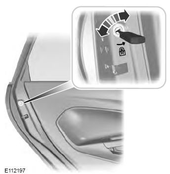
Child Safety Locks
When these locks are set, the rear doors cannot be opened from the inside.

Copyright © 2026 www.fofusion2.com
