Ford Fusion: Supplemental Restraint System / Pinpoint Test - DTC: D. Diagnosis and Testing
B0005:11, B0005:12, B0005:13 and B0005:1A
Refer to Wiring Diagrams Cell 46 for schematic and connector information.
Normal Operation and Fault Conditions
The RCM continuously monitors the collapsible steering column circuits for the following faults:
- Resistance out of range
- Unexpected voltage
- Short to ground
- Faulted collapsible steering column
If a fault is detected, the RCM stores DTC B0005:11, B0005:12, B0005:13 or B0005:1A in memory and sends a message to the IPC to illuminate the airbag warning indicator.
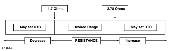
The RCM analyzes the deployment loop resistance to determine if a fault exists. The value displayed in the PID is the deployment loop resistance measured by the RCM. If the value displayed is lower or higher than the desired range (refer to diagram below), the RCM can set a DTC. As the deployment loop resistance drifts farther outside the desired range, the chance for a DTC increases. Small variations in resistance can occur due to the effect of road vibrations on terminal fit. Crimps and terminals can be affected by stress and harness movement and can cause an increase in resistance due to wire strain. These variables can result in an intermittent fault. For this reason, the test requires the PID value to be within the desired range before the fault is considered repaired, regardless if the module is reporting an on-demand DTC at the time of diagnosis. Following this direction helps make sure that minor changes in resistance do not create a repeat concern. This test uses process of elimination to diagnose each part of the deployment loop circuit including:
- Wiring
- Connections
- Collapsible steering column
- RCM
DTC Fault Trigger Conditions
| DTC | Description | Fault Trigger Conditions |
|---|---|---|
| B0005:11 | Collapsible Steering Column Deployment Control: Circuit Short to Ground | A fault is indicated when the RCM senses a short to ground on either collapsible steering column circuit for more than 6 seconds. |
| B0005:12 | Collapsible Steering Column Deployment Control: Circuit Short to Battery | A fault is indicated when the RCM senses a short to voltage on either collapsible steering column circuit for more than 6 seconds. |
| B0005:13 | Collapsible Steering Column Deployment Control: Circuit Open | A fault is indicated when the RCM measures more than the desired resistance range between the collapsible steering column circuits for more than 6 seconds. |
| B0005:1A | Collapsible Steering Column Deployment Control: Circuit Resistance Below Threshold | A fault is indicated when the RCM measures less than the desired resistance range between the collapsible steering column circuits for more than 6 seconds. |
Possible Sources
- Wiring, terminals or connectors
- Collapsible steering column
- RCM
Visual Inspection and Diagnostic Pre-checks
- Inspect for damaged wiring harness(es).
- Inspect for loose or damaged connectors.
PINPOINT TEST A : B0005:11, B0005:12, B0005:13 AND B0005:1A
 WARNING:
Do not handle, move or change the original horizontal
mounting position of the Restraints Control Module (RCM) while the
Restraints Control Module (RCM) is connected and the ignition switch is
ON. Failure to follow this instruction may result in the accidental
deployment of the Safety Canopy® and cause serious personal injury or
death.
WARNING:
Do not handle, move or change the original horizontal
mounting position of the Restraints Control Module (RCM) while the
Restraints Control Module (RCM) is connected and the ignition switch is
ON. Failure to follow this instruction may result in the accidental
deployment of the Safety Canopy® and cause serious personal injury or
death.
|
|||||||||||||
| NOTE: Most faults are due to connector and/or wiring concerns. Carry out a thorough inspection and verification before proceeding with the pinpoint test. | |||||||||||||
| NOTE: Only disconnect or reconnect SRS components when instructed to do so within a pinpoint test step. Failure to follow this instruction may result in incorrect diagnosis of the SRS. | |||||||||||||
| NOTE: Always make sure the correct SRS component is being installed. Parts released for other vehicles may not be compatible even if they appear physically similar. Check the part number listed in the Ford parts catalog to make sure the correct component is being installed. If an incorrect SRS component is installed, Diagnostic Trouble Codes (DTCs) may set. | |||||||||||||
| NOTE: The SRS must be fully operational and free of faults before releasing the vehicle to the customer. | |||||||||||||
| A1 RETRIEVE RCM (RESTRAINTS CONTROL MODULE) DIAGNOSTIC TROUBLE CODES (DTCS) | |||||||||||||
Was DTC B0005:11, B0005:12, B0005:13 or B0005:1A retrieved on-demand during self-test?
|
|||||||||||||
| A2 CHECK THE COLLAPSIBLE STEERING COLUMN DEPLOYMENT CONTROL (DEPLOY_04_R) PID (PARAMETER IDENTIFICATION) | |||||||||||||
Does the PID value read between 1.7 and 2.78 ohms?
|
|||||||||||||
| A3 CHECK THE COLLAPSIBLE STEERING COLUMN DEPLOYMENT CONTROL (DEPLOY_04_R) PID (PARAMETER IDENTIFICATION) WHILE CARRYING OUT THE HARNESS TEST | |||||||||||||
Does the PID value read between 1.7 and 2.78 ohms while carrying out the harness test?
|
|||||||||||||
| A4 CHECK THE COLLAPSIBLE STEERING COLUMN DEPLOYMENT CONTROL DTC (DIAGNOSTIC TROUBLE CODE) FOR A FAULT STATUS CHANGE (LOW RESISTANCE INDICATED) | |||||||||||||
|
NOTE: This pinpoint test step attempts to change the fault reported by the RCM by inducing a different fault condition. If the reported fault changes, this indicates the RCM is functioning correctly and is not the source of the fault.
Did the on-demand DTC change from B0005:1A to B0005:13?
|
|||||||||||||
| A5 CHECK FOR A SHORT BETWEEN THE COLLAPSIBLE STEERING COLUMN CIRCUITS | |||||||||||||
Is the resistance greater than 10,000 ohms?
|
|||||||||||||
| A6 CHECK THE COLLAPSIBLE STEERING COLUMN CIRCUITS FOR AN OPEN | |||||||||||||
Are the resistances less than 0.5 ohm?
|
|||||||||||||
| A7 CHECK THE COLLAPSIBLE STEERING COLUMN DEPLOYMENT CONTROL DTC (DIAGNOSTIC TROUBLE CODE) FOR A FAULT STATUS CHANGE (OPEN INDICATED) | |||||||||||||
|
NOTE: This pinpoint test step attempts to change the fault reported by the RCM by inducing a different fault condition. If the reported fault changes, this indicates the RCM is functioning correctly and is not the source of the fault.
Did the on-demand DTC change from B0005:13 to B0005:1A?
|
|||||||||||||
| A8 CHECK THE COLLAPSIBLE STEERING COLUMN DEPLOYMENT CONTROL DTC (DIAGNOSTIC TROUBLE CODE) FOR A FAULT STATUS CHANGE (SHORT TO GROUND INDICATED) | |||||||||||||
|
NOTE: This pinpoint test step attempts to change the fault reported by the RCM by inducing a different fault condition. If the reported fault changes, this indicates the RCM is functioning correctly and is not the source of the fault.
Did the on-demand DTC change from B0005:11 to B0005:13?
|
|||||||||||||
| A9 CHECK THE COLLAPSIBLE STEERING COLUMN CIRCUITS FOR A SHORT TO GROUND | |||||||||||||
Are the resistances greater than 10,000 ohms?
|
|||||||||||||
| A10 CHECK THE COLLAPSIBLE STEERING COLUMN CIRCUITS FOR A SHORT TO VOLTAGE | |||||||||||||
Is any voltage present?
|
|||||||||||||
| A11 CONFIRM THE COLLAPSIBLE STEERING COLUMN FAULT | |||||||||||||
|
NOTE: Make sure all SRS components and the RCM electrical connectors are connected before carrying out the self-test. If not, Diagnostic Trouble Codes (DTCs) will be recorded.
Was the original DTC retrieved on-demand during self-test?
|
|||||||||||||
| A12 CONFIRM THE RCM (RESTRAINTS CONTROL MODULE) FAULT | |||||||||||||
|
NOTE: Make sure all SRS components and the RCM electrical connectors are connected before carrying out the self-test. If not, Diagnostic Trouble Codes (DTCs) will be recorded.
Was the original DTC retrieved on-demand during self-test?
|
|||||||||||||
| A13 CHECK THE COLLAPSIBLE STEERING COLUMN DEPLOYMENT CONTROL RESISTANCE (DEPLOY_04_R) PID (PARAMETER IDENTIFICATION) FOR AN INTERMITTENT LOW RESISTANCE OR OPEN CIRCUIT FAULT | |||||||||||||
Does the PID value read between 1.7 and 2.78 ohms?
|
|||||||||||||
| A14 CHECK THE COLLAPSIBLE STEERING COLUMN DEPLOYMENT CONTROL CIRCUITS FOR AN INTERMITTENT SHORT TO GROUND FAULT | |||||||||||||
Was DTC B0005:11 retrieved on-demand during self-test?
|
|||||||||||||
| A15 CHECK THE COLLAPSIBLE STEERING COLUMN DEPLOYMENT CONTROL CIRCUITS FOR AN INTERMITTENT SHORT TO BATTERY FAULT | |||||||||||||
Was DTC B0005:12 retrieved on-demand during self-test?
|
|||||||||||||
| A16 CHECK THE HARNESS AND CONNECTORS | |||||||||||||
Were any concerns found?
|
|||||||||||||
| A17 CHECK FOR ADDITIONAL SRS (SUPPLEMENTAL RESTRAINT SYSTEM) DIAGNOSTIC TROUBLE CODES (DTCS) | |||||||||||||
|
Are any RCM, OCSM and/or BECMB Diagnostic Trouble Codes (DTCs) retrieved on-demand during self-test?
|
 WARNING:
Before beginning any service procedure in this
section, refer to Safety Warnings in section 100-00 General Information.
Failure to follow this instruction may result in serious personal
injury.
WARNING:
Before beginning any service procedure in this
section, refer to Safety Warnings in section 100-00 General Information.
Failure to follow this instruction may result in serious personal
injury.


 WARNING:
Turn the ignition OFF and wait one minute to deplete
the backup power supply. Failure to follow this instruction may result
in serious personal injury or death in the event of an accidental
deployment.
WARNING:
Turn the ignition OFF and wait one minute to deplete
the backup power supply. Failure to follow this instruction may result
in serious personal injury or death in the event of an accidental
deployment.

 Pinpoint Test - DTC: E. Diagnosis and Testing
B0010:11, B0010:12, B0010:13 and B0010:1A
Refer to Wiring Diagrams Cell 46 for schematic and connector information.
Normal Operation and Fault Conditions
The RCM continuously monitors the passenger airbag stage 1 circuits for the following faults:
Resistance out of range
Unexpected voltage
Short to ground
Faulted passenger airbag
If a fault is detected, t..
Other information:
Ford Fusion 2013–2020 Owners Manual: Using Tether Straps
Many forward-facing child restraints include a tether strap which extends from the back of the child restraint and hooks to an anchoring point called the top tether anchor. Tether straps are available as an accessory for many older child restraints. Contact the manufacturer of your child restraint for information about ordering a tether strap, or to obtain a longer tether strap if the te..
Ford Fusion 2013–2020 Service Manual: Noise, Vibration and Harshness. Description and Operation
Sound Deadeners and Insulators NOTICE: Mastic is made of a combustible material and should be removed prior to carrying out welding procedures to the area. Heat zones from welding near mastic may cause the mastic material to burn. NOTICE: Corrosion protection must be restored to the area after the mastic material is applied. Corrosion protection products may be wax based and loss of ..
Categories
- Manuals Home
- 2nd Generation Ford Fusion Owners Manual
- 2nd Generation Ford Fusion Service Manual
- Main Control Valve Body. Removal and Installation
- Traction Control
- Garage Door Opener
- New on site
- Most important about car
Understanding Your Tire Pressure Monitoring System
The tire pressure monitoring system measures pressure in your road tires and sends the tire pressure readings to your vehicle. You can view the tire pressure readings through the information display. The low tire pressure warning light will turn on if the tire pressure is significantly low. Once the light is illuminated, your tires are under-inflated and need to be inflated to the manufacturer’s recommended tire pressure. Even if the light turns on and a short time later turns off, your tire pressure still needs to be checked.