Ford Fusion: Exhaust System - 1.5L EcoBoost (118kW/160PS) – I4 / Catalytic Converter. Removal and Installation
Ford Fusion 2013–2020 Service Manual / Powertrain / Exhaust System / Exhaust System - 1.5L EcoBoost (118kW/160PS) – I4 / Catalytic Converter. Removal and Installation
Removal
-
With the vehicle in NEUTRAL, position it on a hoist.
Refer to: Jacking and Lifting - Overview (100-02 Jacking and Lifting, Description and Operation).
-
Remove the battery.
Refer to: Battery (414-01 Battery, Mounting and Cables, Removal and Installation).
-
Remove the HO2S.
Refer to: Heated Oxygen Sensor (HO2S) (303-14A Electronic Engine Controls - 1.5L EcoBoost (118kW/160PS) – I4, Removal and Installation).
-
Remove and discard the catalytic converter bolt.
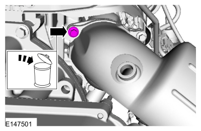 |
-
Remove the catalyst monitor sensor.
Refer to: Catalyst Monitor Sensor (303-14A Electronic Engine Controls - 1.5L EcoBoost (118kW/160PS) – I4, Removal and Installation).
-
Remove the muffler and tailpipe.
Refer to: Muffler and Tailpipe (309-00A Exhaust System - 1.5L EcoBoost (118kW/160PS) – I4, Removal and Installation).
-
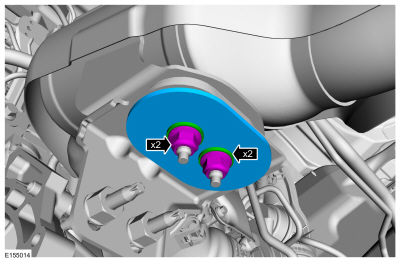
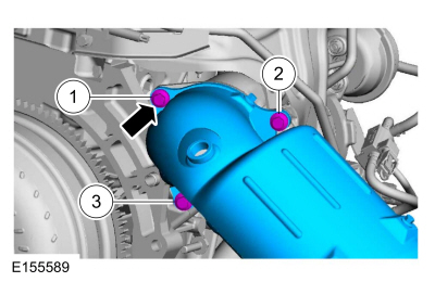
Remove the bolts from the exhaust isolator bracket to the subframe.
 |
-
Remove the nuts and the catalytic converter mounting bracket.
 |
-
-
Remove and discard the catalytic convertor bolts.
-
Remove the catalytic converter.
-
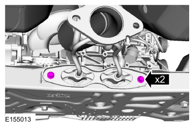
Remove and discard the catalytic convertor bolts.
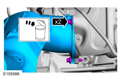 |
-
Remove and discard the catalytic converter to TC gasket.
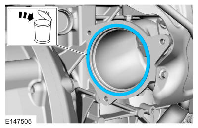 |
Installation
-
Install a new gasket and loosely install the 2 bolts.
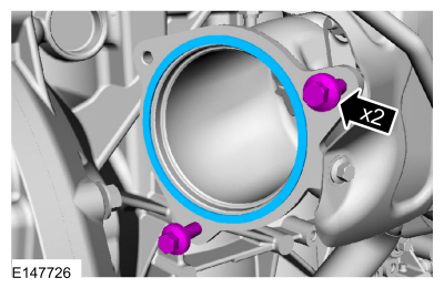 |
-
NOTE: Tighten the catalytic converter bolts in this sequence.
-
Position the catalytic converter on the 2 bolts and install the upper bolt.
Torque: 18 lb.ft (25 Nm)
-
Tighten the RH catalytic converter bolt.
Torque: 18 lb.ft (25 Nm)
-
Tighten the LH catalytic converter bolt.
Torque: 18 lb.ft (25 Nm)
-
Position the catalytic converter on the 2 bolts and install the upper bolt.
 |
-
Install the catalytic converter mounting bracket and the nuts.
Torque: 18 lb.ft (25 Nm)
 |
-
Install the exhaust isolator bracket and bolts to the subframe.
Torque: 18 lb.ft (25 Nm)
 |
-
Install the muffler and tailpipe.
Refer to: Muffler and Tailpipe (309-00A Exhaust System - 1.5L EcoBoost (118kW/160PS) – I4, Removal and Installation).
-
Install the catalyst monitor sensor.
Refer to: Catalyst Monitor Sensor (303-14A Electronic Engine Controls - 1.5L EcoBoost (118kW/160PS) – I4, Removal and Installation).
-
Install the HO2S.
Refer to: Heated Oxygen Sensor (HO2S) (303-14A Electronic Engine Controls - 1.5L EcoBoost (118kW/160PS) – I4, Removal and Installation).
-
Install the battery.
Refer to: Battery (414-01 Battery, Mounting and Cables, Removal and Installation).
 Exhaust System. Diagnosis and Testing
Symptom Chart(s)
Symptom Chart: Symptom Chart - Exhaust System
Verify
the customer concern. Inspect the components of the exhaust system for
obvious signs of damage or other mechanical concerns using the following
chart...
 Muffler and Tailpipe. Removal and Installation
Removal
NOTE:
Removal steps in this procedure may contain installation details.
With the vehicle in NEUTRAL, position it on a hoist.
Refer to: Jacking and Lifting - Overview (100-02 Jacking and Lifting, Description and Operation)...
Other information:
Ford Fusion 2013–2020 Service Manual: Intake Air Temperature (IAT) Sensor. Removal and Installation
Removal NOTE: Removal steps in this procedure may contain installation details. Disconnect the IAT sensor electrical connector and remove the IAT sensor. Installation To install, reverse the removal procedure...
Ford Fusion 2013–2020 Owners Manual: General Information
Have your vehicle serviced regularly to help maintain its roadworthiness and resale value. There is a large network of authorized dealers that are there to help you with their professional servicing expertise. We believe that their specially trained technicians are best qualified to service your vehicle properly and expertly...
Categories
- Manuals Home
- 2nd Generation Ford Fusion Owners Manual
- 2nd Generation Ford Fusion Service Manual
- Load Carrying
- Traction Control
- Body Control Module (BCM). Removal and Installation
- New on site
- Most important about car
Parallel Parking
The system detects available parallel parking spaces and steers your vehicle into the space. You control the accelerator, gearshift and brakes. The system visually and audibly guides you into a parallel parking space.
 Press the button once to search
for a parking space.
Press the button once to search
for a parking space.
Copyright © 2026 www.fofusion2.com