Ford Fusion: Climate Control System - General Information / Receiver Drier Element - 1.5L EcoBoost (118kW/160PS) – I4. Removal and Installation
Special Tool(s) / General Equipment
| Pick Hook | |
| Cable Ties |
Removal
NOTICE: During the removal or installation of components, cap, tape or otherwise appropriately protect all openings and tubes/fittings to prevent the ingress of dirt or other contamination. Remove caps, tape and other protective materials prior to installation.
NOTE: Removal steps in this procedure may contain installation details.
-
Recover the refrigerant. Refer to the appropriate Recovery procedure in Group 412.
-
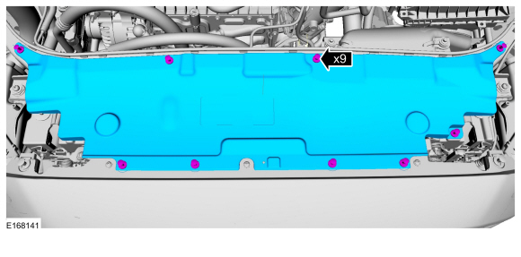
Remove the retainers and the radiator sight shield.
 |
-
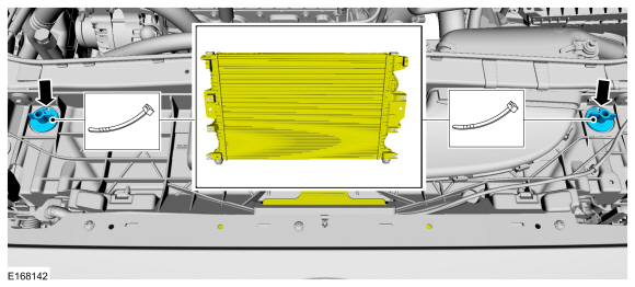
Support each side of the cooling module.
Use the General Equipment: Cable Ties
 |
-
With the vehicle in NEUTRAL, position it on a hoist.
Refer to: Jacking and Lifting - Overview (100-02 Jacking and Lifting, Description and Operation).
-
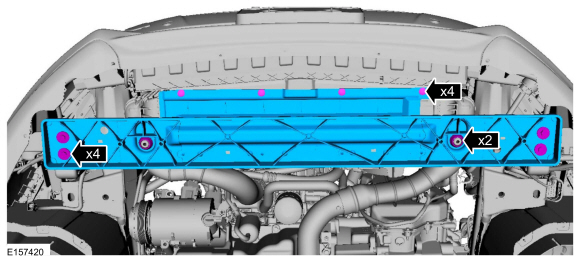
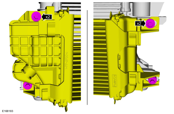
Remove the retainers, bolts, insulators and the cooling module support panel.
Torque: 18 lb.ft (24 Nm)
 |
-
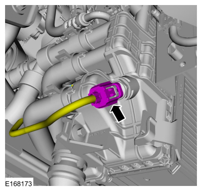
Disconnect the CAC radiator electrical connector.
 |
-
Remove the bolts and position aside the CAC radiator.
Torque: 53 lb.in (6 Nm)
 |
-
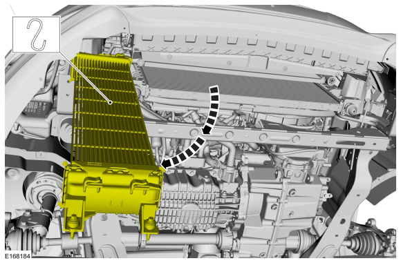
Position aside the CAC.
 |
-
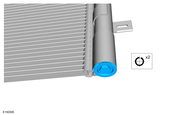
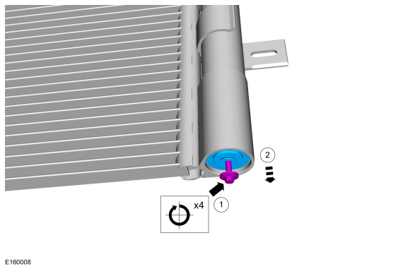
Remove the receiver drier cap.
Loosen:
: 2 turn(s)
 |
-
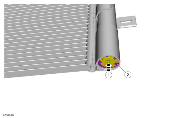
Push the receiver drier plug upwards and remove the receiver drier plug snap ring.
 |
-
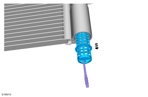
Install and tighten an M5 bolt in the center of the receiver drier plug and remove the receiver drier plug.
 |
-
NOTICE: Make sure that all openings are sealed.
Using a pick tool, remove the receiver drier element.
-
Make sure to cover any open ports to prevent debris from entering the system.
Use the General Equipment: Pick Hook
-
Make sure to cover any open ports to prevent debris from entering the system.
 |
Installation
-
To install, reverse the removal procedure.
-
NOTICE: Only use the specified material to lubricate the seals.
Install and lubricate new O-ring seals. Refer to the appropriate Specifications in Group 412.
-
Lubricate the refrigerant system with the correct amount
of clean PAG oil. Refer to the appropriate Refrigerant Oil Adding
procedure in Group 412.
 Receiver Drier - 2.0L EcoBoost (184kW/250PS) – MI4. Removal and Installation
Removal
NOTICE:
During the removal of components, cap, tape or otherwise
appropriately protect all openings to prevent the ingress of dirt or
other contamination...
 Sunload Sensor. Removal and Installation
Removal
NOTE:
Removal steps in this procedure may contain installation details.
WARNING:
Before beginning any service procedure in this
section, refer to Safety Warnings in section 100-00 General Information...
Other information:
Ford Fusion 2013–2020 Service Manual: Transmission Case Reseal. General Procedures
Special Tool(s) / General Equipment 100-001 (T50T-100-A) Slide Hammer 205-153 (T80T-4000-W) Handle 205-990Installer, Axle SealTKIT-2012A-FLTKIT-2012A-ROW 303-D011 (D80L-100-G) Actuator Pin (Dia 3/16) 303-D019 (D80L-100-Q) Collet, 3/4 to 7/8 307-003 (T57L-500-B) Holding Fixture, Transmission 307-091Handle, Torque ConverterTKIT-2009TC-F ..
Ford Fusion 2013–2020 Service Manual: Climate Control System - Vehicles With: Dual Automatic Temperature Control (DATC). Diagnosis and Testing
Diagnostic Trouble Code (DTC) Charts DTC Chart: Powertrain Control Module (PCM) Diagnostics in this manual assume a certain skill level and knowledge of Ford-specific diagnostic practices. For information about these practices, REFER to: Diagnostic Methods (100-00 General Information, Description and Operation). NOTE: Some PCM Diagnostic Trouble Codes (DTCs) may inhibit A/C operation...
Categories
- Manuals Home
- 2nd Generation Ford Fusion Owners Manual
- 2nd Generation Ford Fusion Service Manual
- Pre-Collision Assist (IF EQUIPPED)
- Front Controls Interface Module (FCIM). Removal and Installation
- Garage Door Opener
- New on site
- Most important about car
Understanding Your Tire Pressure Monitoring System
The tire pressure monitoring system measures pressure in your road tires and sends the tire pressure readings to your vehicle. You can view the tire pressure readings through the information display. The low tire pressure warning light will turn on if the tire pressure is significantly low. Once the light is illuminated, your tires are under-inflated and need to be inflated to the manufacturer’s recommended tire pressure. Even if the light turns on and a short time later turns off, your tire pressure still needs to be checked.