Ford Fusion: Multifunction Electronic Modules / Radio Transceiver Module (RTM). Removal and Installation
Removal
NOTICE: Use care to not crease the headliner during removal and installation or damage to the headliner can occur.
NOTE: Removal steps in this procedure may contain installation details.
-
Refer to: Health and Safety Precautions (100-00 General Information, Description and Operation). WARNING:
Before beginning any service procedure in this
section, refer to Safety Warnings in section 100-00 General Information.
Failure to follow this instruction may result in serious personal
injury.
WARNING:
Before beginning any service procedure in this
section, refer to Safety Warnings in section 100-00 General Information.
Failure to follow this instruction may result in serious personal
injury.
-
On both sides, remove the A-pillar trim panel.
Refer to: A-Pillar Trim Panel (501-05 Interior Trim and Ornamentation, Removal and Installation).
-
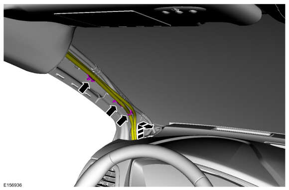
NOTE: Vehicle with roof opening panel shown, vehicle without roof opening panel similar.
Release the clips and position the LH wire harness aside.
 |
-
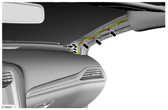
Vehicles equipped with rain sensing wipers.
Release the clips and position the RH wire harness aside.
 |
-
On both sides, remove the B-pillar trim panel.
Refer to: B-Pillar Trim Panel (501-05 Interior Trim and Ornamentation, Removal and Installation).
-
On both sides, remove the C-pillar trim panel.
Refer to: C-Pillar Upper Trim Panel (501-05 Interior Trim and Ornamentation, Removal and Installation).
-
If equipped.
-
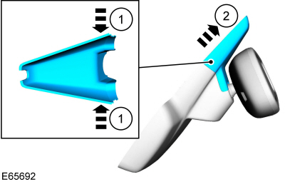
Release the upper rear view mirror cover clips.
-
Remove the upper rear view mirror cover.
-
Release the upper rear view mirror cover clips.
 |
-
If equipped.
Disconnect the rear view mirror electrical connectors.
 |
-
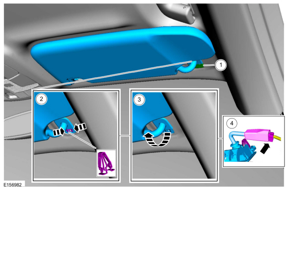
NOTE: RH side shown, LH side similar.
On both sides.
Remove the sun visor.
-
Remove the retainer cover.
-
Release the clip.
-
Remove the sun visor.
-
Disconnect the electrical connector.
-
Remove the retainer cover.
 |
-
NOTE: RH side shown, LH side similar.
On both sides.
Remove the screw and the sun visor clip.
 |
-
All.
Open the screw covers, remove the screws and the grab handle.
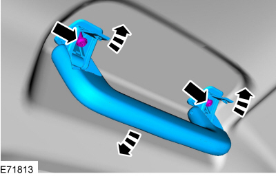 |
-
Release the headliner magnets and lower the headliner.
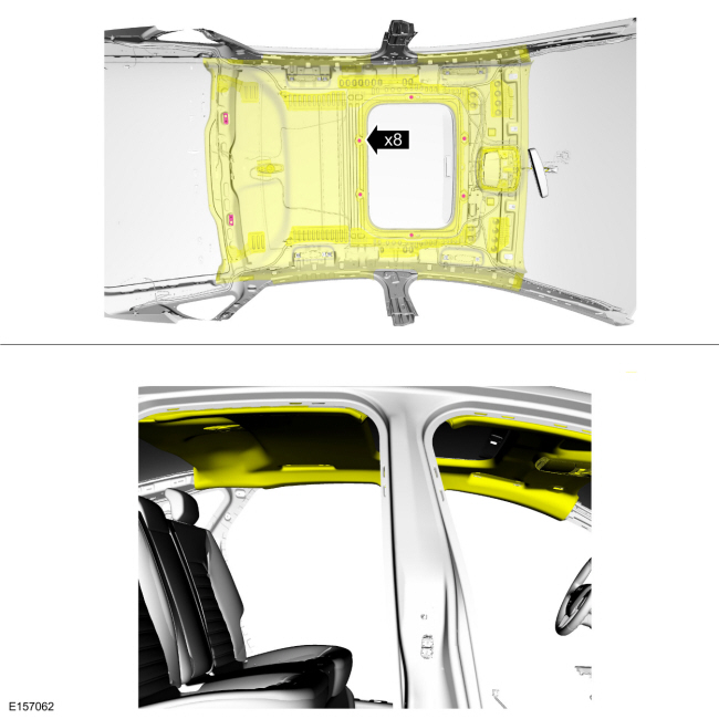 |
-
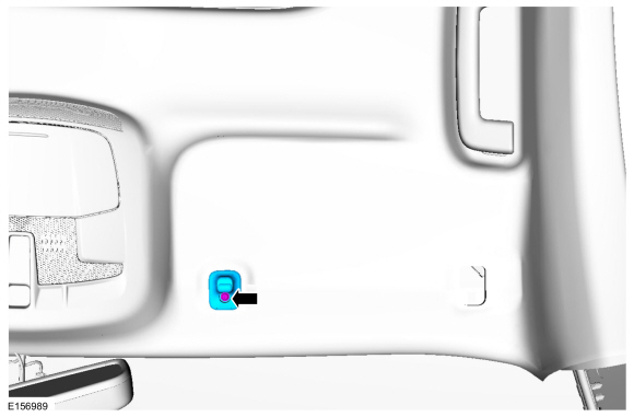
Disconnect the electrical connector, release the tabs and remove the RTM.
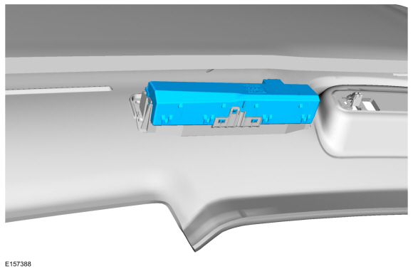 |
Installation
-
NOTE: Transfer parts as necessary.
To install, reverse the removal procedure.
-
NOTE: This step is only necessary when installing a new component.
Using a diagnostic scan tool, complete the PMI process for the RTM following the on-screen instructions.
 Passenger Door Module (PDM). Removal and Installation
Removal
NOTE:
Removal steps in this procedure may contain installation details.
WARNING:
Before beginning any service procedure in this
section, refer to Safety Warnings in section 100-00 General Information...
 Rear Door Module (RDM). Removal and Installation
Removal
NOTE:
Removal steps in this procedure may contain installation details.
WARNING:
Before beginning any service procedure in this
section, refer to Safety Warnings in section 100-00 General Information...
Other information:
Ford Fusion 2013–2020 Owners Manual: Vehicle Storage. Body Styling Kits
Vehicle Storage If you plan on storing your vehicle for 30 days or more, read the following maintenance recommendations to make sure your vehicle stays in good operating condition. We engineer and test all motor vehicles and their components for reliable, regular driving...
Ford Fusion 2013–2020 Service Manual: Wheel Studs. Removal and Installation
Special Tool(s) / General Equipment Hydraulic Press Removal Remove the front wheel bearing and wheel hub. Refer to: Front Wheel Bearing and Wheel Hub (204-01 Front Suspension, Removal and Installation). Press the wheel stud from the wheel bearing and wheel hub...
Categories
- Manuals Home
- 2nd Generation Ford Fusion Owners Manual
- 2nd Generation Ford Fusion Service Manual
- Pre-Collision Assist (IF EQUIPPED)
- Engine
- Transmission - 1.5L EcoBoost (118kW/160PS) – I4. Removal and Installation
- New on site
- Most important about car
Manual Climate Control

Note: Depending on your vehicle option package, the controls may look different from what you see here.