Ford Fusion: Power Steering / Power Steering - System Operation and Component Description. Description and Operation
System Operation
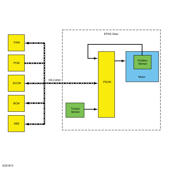
System Diagram
.jpg)
| Item | Description |
|---|---|
| 1 | EPAS gear |
| 2 | HS-CAN2 |
| 3 | EPAS motor |
| 4 | EPAS motor position sensor |
| 5 | EPAS torque sensor |
| 6 | PSCM |
| 7 | PCM |
| 8 | SCCM |
| 9 | ABS module |
| 10 | BCM |
| 11 | PAM |
Network Message Chart
Module Network Input Messages: Power Steering Control Module (PSCM)
| Broadcast Message | Originating Module | Message Purpose |
|---|---|---|
| ABS active | ABS | Used to confirm that the ABS is operational. |
| Power mode | BCM | Used to confirm the ignition status of the vehicle. |
| Stability control brake active | ABS | Used to confirm the operational state of the stability control system. |
| Steering angle counter | SCCM | Used to verify the validity of the steering angle message. |
| Steering angle status | SCCM | Used to confirm the steering angle sensor is initialized and operating correctly. |
| Steering wheel direction of rotation | SCCM | Used to confirm the direction in which the EPAS motor is driven. |
| Traction control brake active | ABS | Used to confirm the operational state of the traction control system. |
| Transport mode | BCM | Used to confirm the vehicle is in normal operation mode, factory mode, transport mode or a crash event has been identified and the vehicle has been set to a post crash configuration. |
| Vehicle configuration/information | ABS | Used to compare the PSCM configuration against the vehicles specific configuration (central car configuration). |
| Vehicle speed | ABS | Used to determine the level of assist supplied. |
| Wheel speed data | ABS | Used to validate the steering wheel component angle by comparing the rotational speeds of each wheel. The difference in the speed of each wheel is used to derive a steering angle for comparison against the absolute steering angle message from the SCCM. |
EPAS System
The PSCM controls the functions of the EPAS system and communicates with other modules over the HS-CAN2.
To activate, the EPAS system needs to be connected to battery voltage at the hot at all times input and at the ignition-run input to the PSCM. In addition, the system must communicate with other modules over the HS-CAN2. The PSCM must receive the power mode signal from the BCM in order to be set into operation mode.
The main input for calculating the level of EPAS assist is the steering torque sensor signal. Vehicle speed is also taken into consideration in order to achieve the vehicle speed dependent steering assist characteristic.
The EPAS gear uses a reversible motor to apply the steering assist. The motor is connected to the rack of the steering gear by a toothed belt and pulley-bearing assembly. The motor is used by the PSCM to move the rack inside the steering gear housing.
The PSCM continually monitors and adjusts steering efforts based on the steering torque sensor signal, motor position and HS-CAN2 inputs to enhance the feel of the steering system. As vehicle speed increases, the amount of assist decreases to improve and enhance road feel at the steering wheel. As vehicle speed decreases, the amount of assist increases to ease vehicle maneuvering. Compensation is made to reduce the effect of pull or drift experienced when driving on roads with a high degree of camber. Also compensation for the impact of wheel imbalance on steering feel is made up to a predetermined threshold.
The steering torque sensor senses the torque at the steering wheel. It is integrated into the PSCM and works by measuring the relative rotation between an input and output shaft which are connected by a torsion bar. The steering torque sensor sends out 2 PWM signals which allows a channel to channel cross-check and an accurate correction of the neutral point.
The PSCM is self-monitoring and is capable of setting and storing Diagnostic Trouble Codes (DTCs). Depending on the DTC set, the PSCM may enter a failure mode. In addition, the PSCM may send a request to the IPC to display a message in the message center, alerting the driver of a potential EPAS concern. The warning message is sent over the HS-CAN2 to the BCM where it is converted to a MS-CAN message and forwarded on to the IPC over the MS-CAN.
Failure Modes
When a DTC is present in the PSCM, the EPAS enters 1 of 2 modes of operation.
The EPAS system enters a reduced steering assist mode to protect the internal components of the system when a non-critical safety concern is detected by the PSCM, concerns such as a loss of the vehicle speed message, low battery voltage, high battery voltage or an over-temperature condition are considered non-critical safety concerns. This reduced steering assist mode gives the steering operation a heavier than normal feel.
The EPAS system enters a manual steering mode (no electrical steering assistance is provided) when a concern considered to be a critical safety concern is detected by the PSCM. In manual steering mode, the vehicle has mechanical steering only which gives the steering operation a heavy feel.
Pull Drift Compensation (PDC)
EPAS equipped vehicles have a Pull Drift Compensation (PDC) feature to assist drivers in compensating for variation in road and driving conditions. The feature adjusts power assist offset by reducing the steering wheel effort (input torque) required to keep the vehicle traveling straight.
The Pull Drift Compensation (PDC) feature is automatically enabled at vehicle speeds above 40 km/h (25 mph) with sensors indicating the vehicle is traveling straight. Pull Drift Compensation (PDC) is designed to compensate for variations in road crown, the system detects input torque to the wheel by the driver to slowly ramp in a steering assist offset to neutralize, in most situations and within limits, steering efforts for the duration of time those driving conditions exist. Full compensation requires up to 45 seconds. Changing lanes on a multilane road and the expected change in road crown would trigger a change in torque input and a compensation adjustment, and is a normal operation of the Pull Drift Compensation (PDC) feature.
The feature updates automatically and continuously, however, since it is based on input torque, the feature only works with both hands on the steering wheel while driving in a straight line. The system does not compensate when turning or during slight curves on highways. The system does not compensate if driver input torque, steering wheel angle or vehicle yaw rate is too large. For the system to compensate, the driver must have both hands on the steering wheel.
Active Park Assist
Some vehicles equipped with EPAS may also be equipped with active park assist. The active park assist system is controlled by the PAM and, when activated, can detect a parking space and steer the vehicle into the space by sending commands to the EPAS
gear (the driver still controls the throttle, brakes and transmission).
The active park assist system is comprised of several systems and
modules working together to aid in parking maneuvers. The presence of
certain Diagnostic Trouble Codes (DTCs) in any of those systems/modules
may either keep the active park assist system from being enabled or may
disable the system if currently being used.
Refer to: Parking Aid - System Operation and Component Description (413-13B Parking Aid - Vehicles With: Active Park Assist, Description and Operation).
Component Description
EPAS Steering Gear
The EPAS gear is an assembly that consists of a PSCM, a motor, and a steering torque sensor, all of which are serviced as an assembly. The inner and outer tie rods and the gear bellows boots are available for service.
- The steering torque sensor is mounted near the input shaft of the EPAS gear and is used by the PSCM to determine how much force is being used to turn the steering wheel.
- The EPAS gear has one inner tie rod located at each end of the gear assembly and is available separately for service.
- The EPAS gear has one outer tie rod located at each end of the gear assembly and is available separately for service.
- The EPAS gear has one bellows boot located at each side of the EPAS gear assembly. Each boot is held in place with 2 boot clamps. The boots and clamps are available for service.
PSCM
The PSCM is the ECU for the EPAS system. The module monitors all sensor inputs and HS-CAN2 messages relating to the EPAS system and directly controls the output of the EPAS motor.

 Steering Gear. Removal and Installation
Removal
NOTE:
Removal steps in this procedure may contain installation details.
If installing a new steering gear, upload the PSCM configuration to the scan tool...
Other information:
Ford Fusion 2013–2020 Service Manual: Subwoofer Amplifier. Removal and Installation
Removal NOTE: Removal steps in this procedure may contain installation details. Remove the parcel shelf. Refer to: Parcel Shelf (501-05 Interior Trim and Ornamentation, Removal and Installation). Remove the bolts and the amplifier...
Ford Fusion 2013–2020 Service Manual: Condenser - 1.5L EcoBoost (118kW/160PS) – I4. Removal and Installation
Removal NOTICE: During the removal or installation of components, cap, tape or otherwise appropriately protect all openings and tubes/fittings to prevent the ingress of dirt or other contamination. Remove caps, tape and other protective materials prior to installation...
Categories
- Manuals Home
- 2nd Generation Ford Fusion Owners Manual
- 2nd Generation Ford Fusion Service Manual
- Memory Function
- Engine
- Automatic Transmission - 6-Speed Automatic Transmission – 6F35
- New on site
- Most important about car
Adjusting the Steering Wheel
WARNING: Do not adjust the steering wheel when your vehicle is moving.
Note: Make sure that you are sitting in the correct position.