Ford Fusion: Parking Aid / Parking Aid - System Operation and Component Description. Description and Operation
System Operation
Parking Aid - Audible
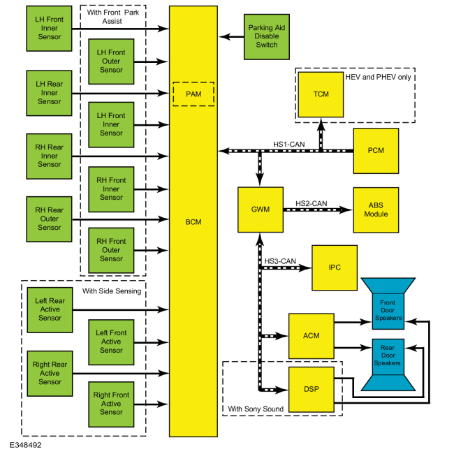
System Diagram
Audible Parking Aid
.jpg)
| Item | Description |
|---|---|
| 1 | TCM |
| 2 | PCM |
| 3 | GWM |
| 4 | IPC |
| 5 | LH front outer sensor |
| 6 | LH front inner sensor |
| 7 | LH front inner sensor |
| 8 | RH front inner sensor |
| 9 | RH rear outer sensor |
| 10 | RH front outer sensor |
| 11 | RH rear inner sensor |
| 12 | LH rear inner sensor |
| 13 | Right front active sensor |
| 14 | Left front active sensor |
| 15 | Right rear active sensor |
| 16 | With front park assist |
| 17 | With side sensing |
| 18 | Rear door speakers |
| 19 | Front door speakers |
| 20 | BCM |
| 21 | ABS module |
| 22 | ACM |
| 23 | DSP |
| 24 | With Sony Sound |
| 25 | PAM |
| 26 | HEV and PHEV only |
| 27 | Parking aid disable switch |
| 28 | Left rear active sensor |
Network Message Chart
PAM Network Input Messages
| Broadcast Message | Originating Module | Message Purpose |
|---|---|---|
| Ambient air temperature | PCM | Used to temperature compensate the parking aid sensors |
| Decklid ajar status | BCM | Used to indicate that the hood is opened. |
| Electrical power status | SOBDMC | Used to indicate if the engine is on (for HEV/ PHEV). |
| Ignition key type | BCM | Used to disable the parking aid menus if a MyKey® is in use |
| Ignition status | BCM | Used to communicate the ignition switch state. |
| Parking aid enable request | IPC | Used to enable or disable the front or rear parking aid. |
| Parking aid enable status | BCM | Used to enable or disable the front or rear parking aid. |
| Selector lever (PRNDL) status (HEV only) | TCM | Used to enable the parking aid when the transmission selector is in REVERSE on hybrid vehicles. |
| Selector lever (PRNDL) status (except HEV) | PCM | Used to enable the parking aid when the transmission selector is in REVERSE. |
| Wheel rotation count | ABS module | Used to disable and enable the parking aid system based on vehicle speed. |
ACM Network Input Messages
| Broadcast Message | Originating Module | Message Purpose |
|---|---|---|
| Chime source | IPC | Used to command parking aid warning tones through the audio system speakers. |
DSP Network Input Messages
| Broadcast Message | Originating Module | Message Purpose |
|---|---|---|
| Chime source | IPC | Used to command parking aid warning tones through the audio system speakers. |
IPC Network Input Messages
| Broadcast Message | Originating Module | Message Purpose |
|---|---|---|
| Parking aid chime request | PAM | Used to command parking aid warning tones through the audio system speakers. |
| Parking aid enable status | BCM | Used to indicate to the IPC that the front or rear parking aid is enabled or disabled. |
| Parking aid status | PAM | Used to command parking aid warning tones through the audio system speakers. |
| Parking aid sensor status | PAM | Used parking aid status. |
Audible Parking Aid System Operation
The PAM calculates the distance to an object within a 170 degree semicircular area (azimuth) around the front and/or rear of the vehicle. When an object is detected by the front or rear parking aid system, a variable rate warning tone is sounded through the corresponding audio system speakers (front or rear door speakers).
The rear parking aid system calculates the distance to an object around the rear of the vehicle using 4 ultrasonic sensors. The rear parking aid sensors detect objects approximately 1,524 mm (60 in) from the rear of the vehicle, 508 mm (20 in) from the rear side of the vehicle, and 305 mm (12 in) above the ground. To detect objects behind the vehicle, the PAM supplies voltage and ground to the rear ultrasonic sensors while monitoring a signal return circuit from each sensor. The 4 rear sensors share common voltage and ground circuits.
This vehicle may also be equipped with a front parking aid system. The front parking aid system calculates the distance to an object around the front of the vehicle using 4 ultrasonic sensors. The front parking aid sensors detect objects approximately 686 mm (27 in) from the front of the vehicle, 457 mm (18 in) from the front side of the vehicle, 305 mm (12 in) above the ground. To detect objects in front of the vehicle, the PAM supplies voltage and ground to the front ultrasonic sensors while monitoring a signal return circuit from each sensor. The 4 front sensors share common voltage and ground circuits.
Only objects that reflect a sufficient amount of sound waves are detected by the front or rear parking aid sensors. The surface properties, size and composition an object can affect the ability of the parking aid system to detect the object. Incorrect sensor alignment or installation, dirt or ice covered sensors, heavy rain and snow can also cause objects not to be detected.
Side Sensing
The side sensing system calculates the distance to an object around the sides of the vehicle using the four active parking aid sensors used for the active park assist. The side sensors detect objects approximately 60 cm (24 in) from the side of the vehicle. To detect objects on the sides of the vehicle, the PAM supplies voltage and ground to the front ultrasonic sensors while monitoring a signal return circuit from each sensor. The 2 front side sensors share common voltage and ground circuits with the front parking aid sensors. The 2 rear side sensors share common voltage and ground circuits with the rear parking aid sensors.
Parking Aid Audible Alert
The parking aid audible tones are sounded through the audio system speakers. For the rear parking aid only the audio system volume is automatically reduced when a parking aid alert tone is sounded. The audio speaker increases its warning tone rate as the vehicle gets closer to an obstacle. When an object is detected within 305 mm (12 in) of the sensors, the warning tone becomes continuous. Objects to the rear side generate a continuous tone for only 3 seconds if the object is stationary or receding from the vehicle. The warning tones are prioritized to the system (front or rear) which has detected an object closest to the bumper. The tone will alternate between front and rear audio speakers if objects are detected closer than 254 mm (10 in) front and rear.
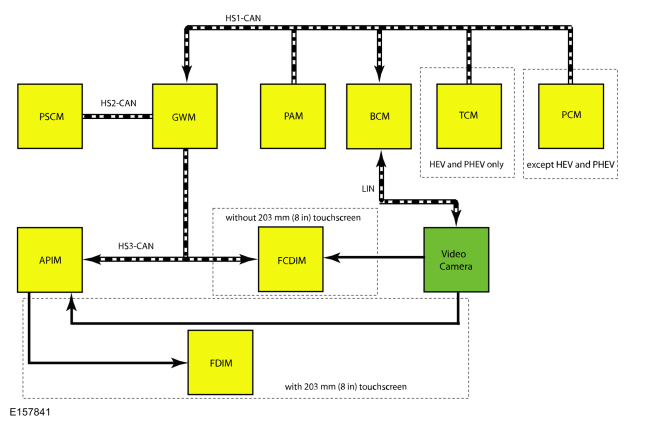
Parking Aid - Video
System Diagram
Network Message Chart
BCM Network Input Messages
| Broadcast Message | Originating Module | Message Purpose |
|---|---|---|
| Camera commands (vehicles with 203 mm (8 in) touchscreen) | APIM | Used to command the static and active guidelines status and zoom. |
| Camera commands (vehicles without 203 mm (8 in) touchscreen) | FCDIM | Used to command the static and active guidelines status and zoom. |
| Parking aid range to object | PAM | Used to highlight the zone where an object is detected. |
| Selector lever (PRNDL) status (HEV and PHEV only) | TCM | Used to enable and disable the rear video display on hybrid vehicles. |
| Selector lever (PRNDL) status (except HEV and PHEV) | PCM | Used to enable and disable the rear video display. |
| Steering angle status | PSCM | Used to create the vehicle intended path on video display. |
Accessory Protocol Interface Module (APIM) Network Input Messages
| Broadcast Message | Originating Module | Message Purpose |
|---|---|---|
| Backup camera status | BCM | Used to display the video status for static and active guidelines and zoom level. |
Image Display
The decklid must remain closed for correct operation of the video camera system.
The video camera system has 5 user-selectable features:
- Fixed guidelines — assists the driver with aligning the vehicle with an object.
- Active guidelines — displays the intended path of the vehicle based upon steering wheel input.
- Visual park aid alert — assists the driver to visually see the object causing the parking aid system to sound.
- Manual zoom — assists the driver with connecting or towing a trailer allowing the driver to manually zoom closer to an object behind the vehicle.
- Video camera delay — allows the driver to see the image behind the vehicle after the vehicle is shifted out of REVERSE. The image will not be displayed if the vehicle is shifted into PARK.
On vehicles equipped with the 203 mm (8 in) touchscreen, the camera commands controlled by the driver are generated at the FDIM which is hardwired to the APIM. On vehicles not equipped with a 203 mm (8 in) touchscreen, the camera commands controlled by the driver are generated at the FCDIM. The camera commands are then sent to the BCM. The BCM sends the command to the video camera via the LIN circuit. On vehicles equipped with a 203 mm (8 in) touchscreen, the video camera outputs the video signal to the APIM, which is directly connected to the FDIM, which displays the image. On vehicles not equipped with a 203 mm (8 in) touchscreen, the video camera outputs the video signal to the FCDIM, which displays the image.
The BCM and the video camera communicate via a LIN circuit which is a dedicated single wire communication network.
The messages sent from the BCM to the video camera are:
- Transmission in reverse
- Decklid ajar status
- Camera configuration data
- Display manual zoom request
- Parking aid audible warning status
- Parking aid sensor distance to object data
The messages sent from the video camera to the BCM are:
- Camera status
- Display zoom status
- Camera part number data
- Visual park aid alert status
- Fixed guideline status
Visual Park Aid
The visual park aid alert feature utilizes the rear parking aid sensor inputs from the PAM and the video camera image. When the transmission selector is in REVERSE and an object is detected by a rear parking aid sensor, parking aid range to object data is sent from the PAM through the BCM to the video camera.
The visual alerts are red, yellow or green and appear as highlights on top of the displayed image to indicate in which zone the object is detected. If the visual park aid alert feature is enabled, the highlighted visual alerts are still operational even if the parking aid system has been disabled by the driver.
Fixed Guidelines
NOTE: The color-coded lines cannot indicate accurate or consistent distances between objects located behind the vehicle and at the rear of the vehicle. This normal condition is due to variances in vehicle ride height, including, but not limited to, vehicle loading.
The video camera fixed guidelines feature displays guidelines on top of the video image to assist the driver with alignment of the vehicle. A dashed line on the displayed image represents the center of the vehicle and 3 color-coded lines (red, yellow, green) identify different zones between the rear of the vehicle and objects.
Active Guidelines
The video camera active guidelines feature displays guidelines on top of the video image to assist the driver with maneuvering a vehicle into a space. Active guidelines are not shown when the steering wheel is straight.
NOTE: If the battery has been disconnected or discharged, or a module is disconnected or replaced, the active guidelines may be inoperative until the vehicle is driven on a flat and smooth road at 32 km/h (20 mph) or more, with hands placed loosely on the steering wheel and minimal steering correction for approximately 30 seconds.
If the guidelines are remain inoperative, it may be necessary to disconnect the battery for 5 minutes with the driver's door open, then drive the vehicle for 5 miles in normal city driving before performing the procedure described above.Manual Zoom
The manual zoom feature is controlled by the video camera. The manual zoom feature has 1 zoom levels that are only active when the vehicle is in REVERSE. If the manual zoom feature is enabled and the vehicle is shifted out of REVERSE the manual zoom feature is disabled. The manual zoom feature must be re-enabled the next time the vehicle is shifted into REVERSE.
Video Delay
When the video delay is turned on, the video image remains displayed after the transmission is shifted out of REVERSE, into any gear other than PARK, until the vehicle speed reaches 10 km/h (7 mph). With the delay off (default), the image displays until the transmission is shifted out of REVERSE.
Component Description
Parking Aid Sensors
The parking aid sensors are wide beam ultrasonic sensors. The sensors continuously send out ultrasonic signals to detect objects and communicate the information back to the PAM.
Only objects which reflect enough sound waves are detected by the sensors. This varies due to the shape, surface properties and size of objects being detected. Incorrect sensor alignment, dirt covered sensors, heavy rain and snow can cause objects not to be recognized.
PAM
The PAM calculates and reports (via audio system tones) the distance between the front or rear bumper of the vehicle and an object. The PAM is integral to the BCM and requires PMI when replaced.
Video Camera
The rear video camera system is active with the ignition in RUN and the transmission selector in REVERSE. The video camera receives commands and sends status over a dedicated LIN to the BCM. After replacement, the video camera must be configured through the BCM using a diagnostic scan tool.
 Parking Aid - Overview. Description and Operation
Parking Aid - Audible
The
rear parking aid system sounds a warning tone through the rear audio
speakers to alert the driver of stationary objects near the rear bumper
when reverse is selected...
 Parking Aid. Diagnosis and Testing
DTC Chart: Parking Aid Module (PAM)
Diagnostics in this manual assume a certain skill level and knowledge of Ford-specific diagnostic practices. REFER to: Diagnostic Methods (100-00 General Information, Description and Operation)...
Other information:
Ford Fusion 2013–2020 Service Manual: Clockspring Adjustment. General Procedures
WARNING: If the clockspring is not correctly centralized, it may fail prematurely. If in doubt, repeat the centralizing procedure. Failure to follow these instructions may increase the risk of serious personal injury or death in a crash...
Ford Fusion 2013–2020 Service Manual: Seatbelt Retractor and Pretensioner. Removal and Installation
Removal NOTE: Removal steps in this procedure may contain installation details. NOTE: RH shown, LH similar. Position the front seat in the full forward position. WARNING: Turn the ignition OFF and wait one minute to deplete the backup power supply...
Categories
- Manuals Home
- 2nd Generation Ford Fusion Owners Manual
- 2nd Generation Ford Fusion Service Manual
- Starter Motor. Removal and Installation
- Intake Manifold. Removal and Installation
- Engine
- New on site
- Most important about car
Manual Climate Control

Note: Depending on your vehicle option package, the controls may look different from what you see here.