Ford Fusion: Parking Brake and Actuation / Parking Brake Switch. Removal and Installation
Ford Fusion 2013–2020 Service Manual / Chassis / Brake System / Parking Brake and Actuation / Parking Brake Switch. Removal and Installation
Special Tool(s) / General Equipment
| Interior Trim Remover |
Removal
NOTE: Removal steps in this procedure may contain installation details.
-
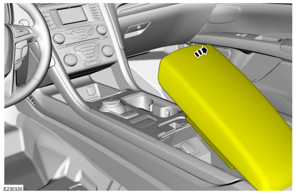
Open the floor console stowage bin lid.
 |
-
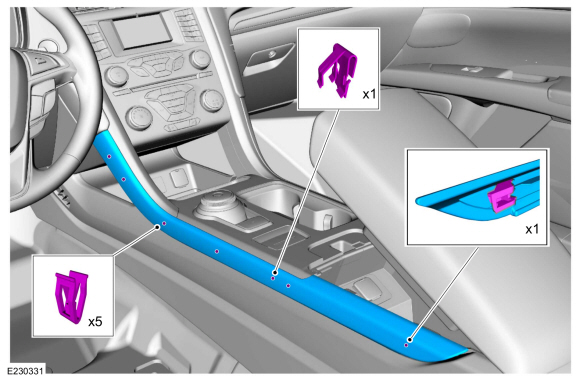
On both sides.
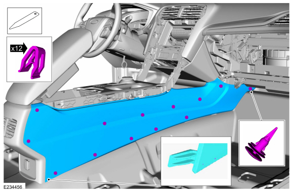
Detach the clips and remove the floor console upper side finish panels.
 |
-
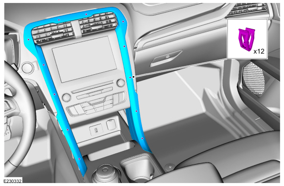
Detach the clips and remove the instrument panel center finish panel.
 |
-
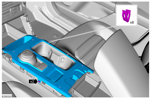
Remove the screws, detach the clips and remove the upper floor console finish panel.
 |
-
NOTE: RH side shown, LH side similar.
On both sides.
Release the push pin, clips starting from front to rear. Disengage the finger tab at the bottom rear corner and remove the floor console side trim panel.
Use the General Equipment: Interior Trim Remover
 |
-
-
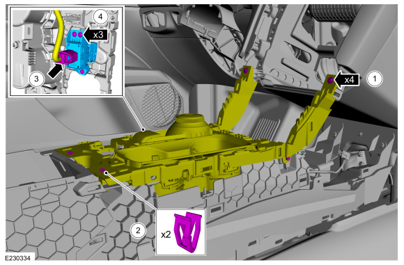
Remove the screws.
-
Detach the clips and position the floor console upper support to access the parking brake switch.
-
Disconnect the electrical connector.
-
Remove the parking brake switch.
-
Remove the screws.
 |
Installation
-
To install, reverse the removal procedure.
-
NOTE: Anytime the parking brake switch electrical connector has been disconnected, the EPB system is deactivated and a DTC is stored in the ABS module. Perform the following step to restore the EPB system and clear the ABS module DTC.
Apply and release the parking brake twice within 5 seconds, pausing with the switch in the NEUTRAL position for approximately one-half second between each apply and release.
 Parking Brake Actuator Motor. Removal and Installation
Removal
NOTE:
Removal steps in this procedure may contain installation details.
With the vehicle in NEUTRAL, position it on a hoist.
Refer to: Jacking and Lifting - Overview (100-02 Jacking and Lifting, Description and Operation)...

Other information:
Ford Fusion 2013–2020 Service Manual: SYNC Module [APIM] to Front Display Interface Module (FDIM) Cable. Removal and Installation
Removal Remove the FDIM. Refer to: Front Display Interface Module (FDIM) (415-00 Information and Entertainment System - General Information - Vehicles With: SYNC 3, Removal and Installation). Disconnect the electrical connectors and remove the APIM to FDIM cable. Installation To install, reverse the removal procedure. ..
Ford Fusion 2013–2020 Owners Manual: SYNC™ Troubleshooting
Your SYNC system is easy to use. However, should questions arise, see the tables below. Use your regional Ford website at any time to check your phone's compatibility, register your account and set preferences as well as access a customer representative via an online chat (during certain hours). ..
Categories
- Manuals Home
- 2nd Generation Ford Fusion Owners Manual
- 2nd Generation Ford Fusion Service Manual
- Main Control Valve Body. Removal and Installation
- Garage Door Opener
- Traction Control
- New on site
- Most important about car
Parallel Parking
The system detects available parallel parking spaces and steers your vehicle into the space. You control the accelerator, gearshift and brakes. The system visually and audibly guides you into a parallel parking space.
 Press the button once to search
for a parking space.
Press the button once to search
for a parking space.
Copyright © 2026 www.fofusion2.com