Ford Fusion: Instrument Panel and Console / Instrument Panel Upper Section. Removal and Installation
Special Tool(s) /
General Equipment
Removal
NOTE:
Removal steps in this procedure may contain installation details.
-
 WARNING:
Before beginning any service procedure in this
section, refer to Safety Warnings in section 100-00 General Information.
Failure to follow this instruction may result in serious personal
injury.
WARNING:
Before beginning any service procedure in this
section, refer to Safety Warnings in section 100-00 General Information.
Failure to follow this instruction may result in serious personal
injury.
Refer to: Health and Safety Precautions (100-00 General Information, Description and Operation).
-
NOTE:
The instrument panel must be removed from the vehicle prior to removing the instrument panel upper section.
Remove the instrument panel.
Refer to: Instrument Panel (501-12 Instrument Panel and Console, Removal and Installation).
-
Remove the steering column.
Refer to: Steering Column (211-04 Steering Column, Removal and Installation).
-
Remove the bolts, release the clips and lower the instrument panel trim panel.
Torque:
22 lb.in (2.5 Nm)
-
Disconnect the headlamp switch electrical connector and remove the instrument panel trim panel.
-
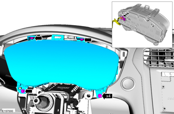
Remove the bolts, release the clips and remove the IPC bezel.
Torque:
22 lb.in (2.5 Nm)
-
Remove the bolts and the IPC. Disconnect the electrical connector.
Torque:
27 lb.in (3 Nm)
-
Remove the FCDIM or the FDIM.
Refer to: Front Control/Display Interface Module (FCDIM)
(415-00 Information and Entertainment System - General Information)
.
Refer to: Front Display Interface Module (FDIM) (415-00 Information and Entertainment System - General Information - Vehicles With: SYNC 3, Removal and Installation).
Refer to: Front Display Interface Module (FDIM) (415-00
Information and Entertainment System - General Information)
.
-
If equipped.
Remove the engine start stop button and disconnect the electrical connector.
Use the General Equipment: Interior Trim Remover
-
Remove the ACM.
Refer to: Audio Front Control Module (ACM) (415-00 Information and Entertainment System - General Information)
.
Refer to: Audio Front Control Module (ACM) (415-00 Information and Entertainment System - General Information - Vehicles With: SYNC 3, Removal and Installation).
Refer to: Audio Front Control Module (ACM) (415-00 Information and Entertainment System - General Information)
.
-
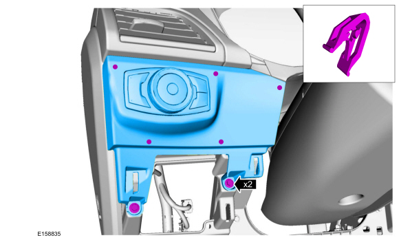
Remove the bolts and the center register. Disconnect the electrical connector.
Torque:
22 lb.in (2.5 Nm)
-
Release the clips and remove the RH instrument panel finish panel.
Use the General Equipment: Interior Trim Remover
-
Remove the bolts, release the retaining tabs and remove
the glove compartment. Disconnect the electrical connector.
Torque:
22 lb.in (2.5 Nm)
-
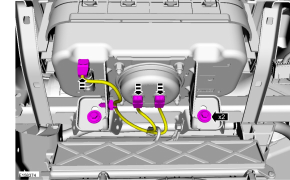
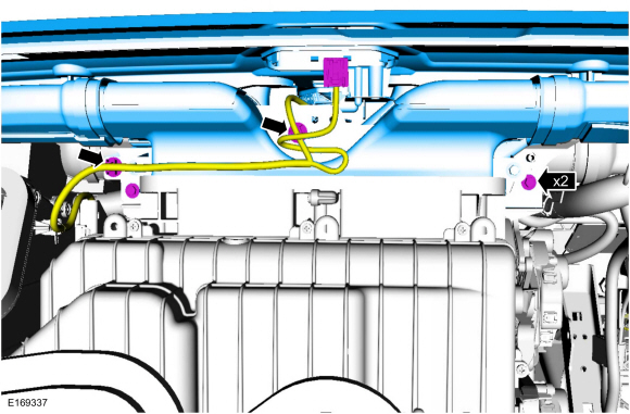
Remove the bolts, disconnect the electrical connectors, release the harness retainer and position aside harness.
Torque:
93 lb.in (10.5 Nm)
-
If equipped, remove the instrument panel center speaker.
Refer to: Instrument Panel Center Speaker (415-00 Information and Entertainment System - General Information - Vehicles With: SYNC 3, Removal and Installation).
-
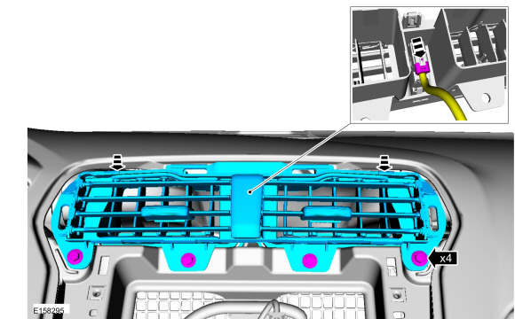
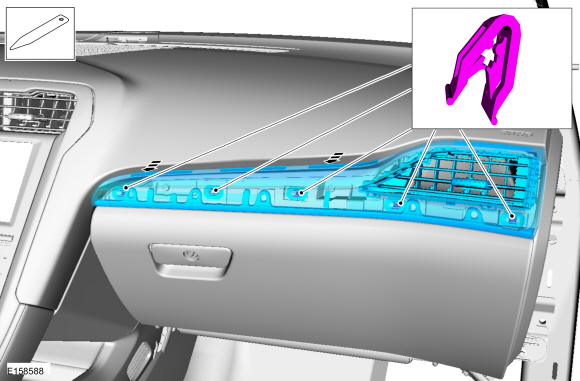
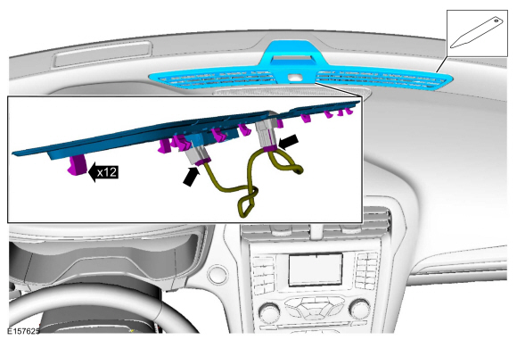
Release the clips and remove the defroster grille panel. Disconnect the electrical connectors.
Use the General Equipment: Interior Trim Remover
-
Remove the HUD module.
Refer to: Head Up Display (HUD) Module (419-03B Collision Warning and Collision Avoidance System, Removal and Installation).
-
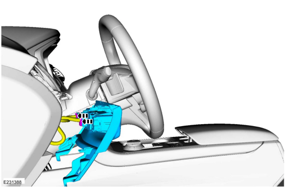
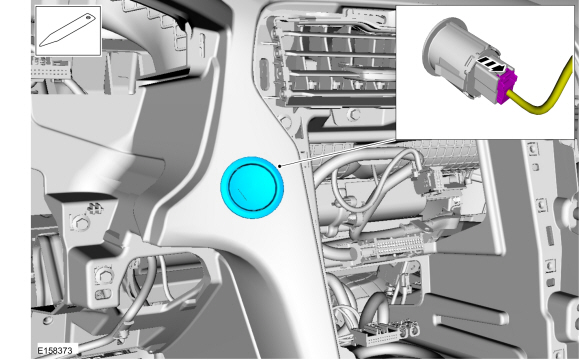
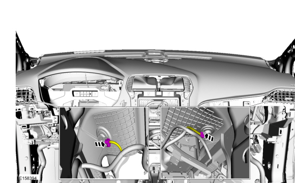
Disconnect the electrical connectors.
-
Remove the bolts, disconnect the electrical connector and release wiring harness retainers.
-
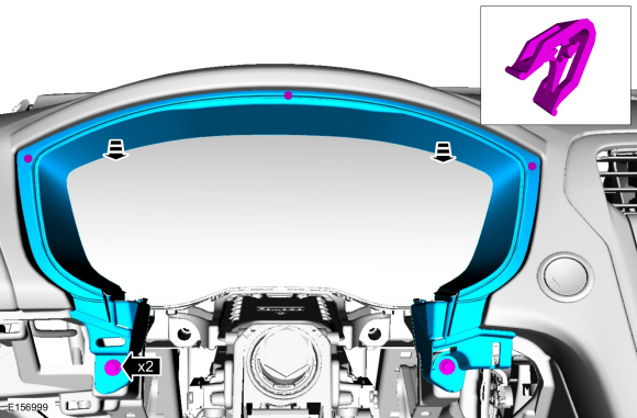
NOTE:
To avoid damaging the instrument panel, an assistant is required when carrying out this step.
NOTE:
Make sure that all electrical connectors and wiring
are not hindered before removing the upper section or damage to the
components may occur.
NOTE:
Install all the bolts finger tight before final tightening.
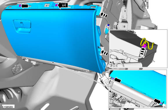
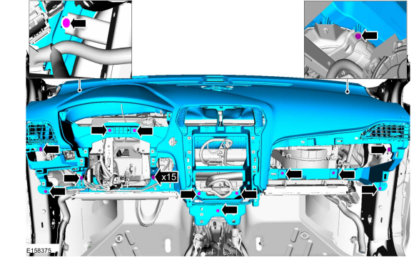
Remove the bolts and the instrument panel upper section.
Torque:
22 lb.in (2.5 Nm)
Installation
-
To install, reverse the removal procedure.
Special Tool(s) /
General Equipment
Hose Clamp(s)
Interior Trim Remover
Removal
NOTE:
Removal steps in this procedure may contain installation details...
Removal
NOTE:
Removal steps in this procedure may contain installation details.
NOTE:
Consoles look different depending on option level.
Insert trim tool in location(s) shown...
Other information:
Removal
WARNING:
Before beginning any service procedure in this
section, refer to Safety Warnings in section 100-00 General Information.
Failure to follow this instruction may result in serious personal
injury.
Follow the health and safety precautions...
Disconnect
NOTE:
When reusing liquid or vapor tube connections, make sure to
use compressed air to remove any foreign material from the connector
retaining clip area before separating from the tube or damage to the
tube or connector retaining clip may occur...
 Instrument Panel. Removal and Installation
 Overhead Console. Removal and Installation