
Ford Fusion: Horn / Horn - Component Location. Description and Operation
Ford Fusion 2013–2020 Service Manual / Electrical / Instrumentation and Warning Systems / Horn / Horn - Component Location. Description and Operation

| Item | Description |
|---|---|
| 1 | Horn Comments: Located behind the front bumper cover |
 Horn
..
 Horn - Overview. Description and Operation
Overview
The BCM controls horn output by energizing the integrated horn relay located in the BJB and sounding the horn...
Other information:
Ford Fusion 2013–2020 Service Manual: External Controls - System Operation and Component Description. Description and Operation
System Diagram Item Description 1 GWM 2 GSM 3 Overrride Switch 4 TRCM 5 PCM 6 BCM 7 Driver Door Module 8 IPC 9 RCM Network Message Chart Broadcast Message Originating Module Message Purpose Brake switch position GSM Input from brake switch necessary to change gears. Gear data GSM Messag..
Ford Fusion 2013–2020 Service Manual: Symbols Glossary. Description and Operation
Symbols are used inside the graphics and in the text area to enhance the information display. Movement Symbols Movement symbols provide detailed information to a required component movement. These component movements can be rotational or 1-3 dimensional movements. Item Part Number Description 1 — Minor component movement clockwise/counterclockwise ..
Categories
- Manuals Home
- 2nd Generation Ford Fusion Owners Manual
- 2nd Generation Ford Fusion Service Manual
- Main Control Valve Body. Removal and Installation
- Electrical
- Transmission Fluid Drain and Refill. General Procedures
- New on site
- Most important about car
Direction Indicators. Interior Lamps
Direction Indicators
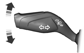
Push the lever up or down to use the direction indicators.

Copyright © 2026 www.fofusion2.com