Ford Fusion: Climate Control System - General Information / Heater Core Leak Check - Vehicles With: R1234YF Refrigerant. General Procedures
Ford Fusion 2013–2020 Service Manual / Electrical / Climate Control System / Climate Control System - General Information / Heater Core Leak Check - Vehicles With: R1234YF Refrigerant. General Procedures
Inspection
-
NOTE: A coolant leak in the heater hose could follow the heater core tube to the heater core and appear as a leak in the heater core.
Inspect for evidence of coolant leakage at the heater hose to heater core attachments.
-
NOTE: Spring-type clamps are installed as original equipment. Installation and overtightening of nonspecified clamps can cause leakage at the heater hose connection and damage the heater core.
Check the integrity of the heater hose clamps.
-
Drain the coolant from the cooling system. Refer to
Cooling System Draining, Filling, and Bleeding procedure in Group 303.
-
Disconnect the heater hoses from the heater core.
-
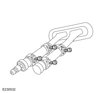
Install a short piece of heater hose, approximately 101 mm (4 in) long on each heater core tube.
-
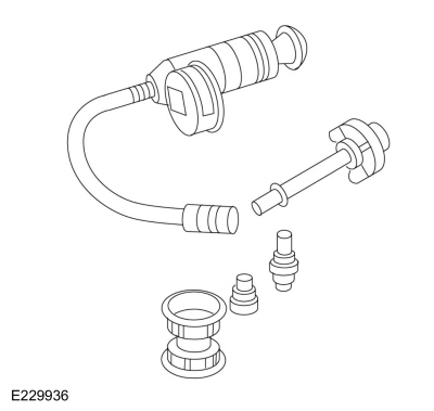
Fill the heater core and heater hoses with water and
install the plug (221373) and the adapter (221374) from the Pressure
Test Kit. Secure the heater hoses, plug and adapter with hose clamps.
 |
-
Attach the pump and gauge assembly from the Pressure Test Kit to the adapter.
-
014-R1072 Radiator Pressure Test Set
-
014-R1072 Radiator Pressure Test Set
 |
-
Close the bleed valve at the base of the gauge. Pump 138 kPa (20 psi) of air pressure into the heater core.
-
Observe the pressure gauge for a minimum of 3 minutes.
-
If the pressure drops, check the heater hose connections
to the heater core tubes for leaks. If the heater hoses do not leak,
replace the heater core.
 Fluorescent Dye Leak Detection - Vehicles With: R1234YF Refrigerant. General Procedures
Special Tool(s) /
General Equipment
UV Leak Detector
Electronic Leak Detector
Leak detection
Vehicles with air conditioning
Review next note for important refrigerant system dye information...
 Refrigerant Identification Testing - Vehicles With: R1234YF Refrigerant. General Procedures
Special Tool(s) /
General Equipment
Refrigerant Identification Equipment
Activation
NOTE:
Use Refrigerant Identification Equipment to identify
gas samples taken directly from the refrigeration system or storage
containers prior to recovering or charging the refrigerant system...
Other information:
Ford Fusion 2013–2020 Service Manual: D-Pillar Trim Panel. Removal and Installation
Special Tool(s) / General Equipment Interior Trim Remover Removal Release the clips and remove the D-pillar trim panel. Use the General Equipment: Interior Trim Remover Installation To install, reverse the removal procedure...
Ford Fusion 2013–2020 Service Manual: Front Strut and Spring Assembly. Removal and Installation
Removal NOTICE: Suspension fasteners are critical parts that affect the performance of vital components and systems. Failure of these fasteners may result in major service expense. Use the same or equivalent parts if replacement is necessary. Do not use a replacement part of lesser quality or substitute design...
Categories
- Manuals Home
- 2nd Generation Ford Fusion Owners Manual
- 2nd Generation Ford Fusion Service Manual
- Traction Control
- Cylinder Head. Removal and Installation
- Main Control Valve Body. Removal and Installation
- New on site
- Most important about car
Using Seatbelts During Pregnancy
WARNING: Always ride and drive with your seatback upright and properly fasten your seatbelt. Fit the lap portion of the seatbelt snugly and low across the hips. Position the shoulder portion of the seatbelt across your chest. Pregnant women must follow this practice. See the following figure.

Copyright © 2025 www.fofusion2.com