Ford Fusion: Electronic Engine Controls - 1.5L EcoBoost (118kW/160PS) – I4 / Heated Oxygen Sensor (HO2S). Removal and Installation
Ford Fusion 2013–2020 Service Manual / Powertrain / Engine / Electronic Engine Controls - 1.5L EcoBoost (118kW/160PS) – I4 / Heated Oxygen Sensor (HO2S). Removal and Installation
Special Tool(s) / General Equipment
 |
303-476
(T94P-9472-A)
Socket, Exhaust Gas Oxygen Sensor TKIT-1994-LM/M TKIT-1994-F TKIT-1994-FLM/FM |
Materials
| Name | Specification |
|---|---|
| Motorcraft® High Temperature Nickel Anti-Seize Lubricant XL-2 |
- |
| Motorcraft® Penetrating and Lock Lubricant XL-1 |
- |
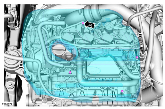
Removal
-
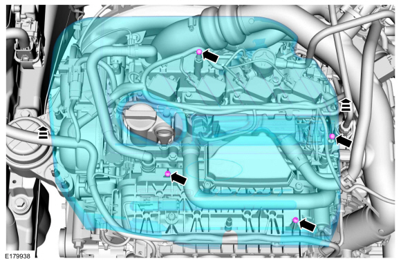
Remove the engine appearance cover.
 |
-
Remove the air cleaner outlet pipe.
Refer to: Air Cleaner Outlet Pipe (303-12A Intake Air Distribution and Filtering - 1.5L EcoBoost (118kW/160PS) – I4, Removal and Installation).
-
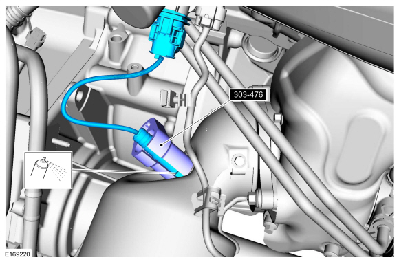
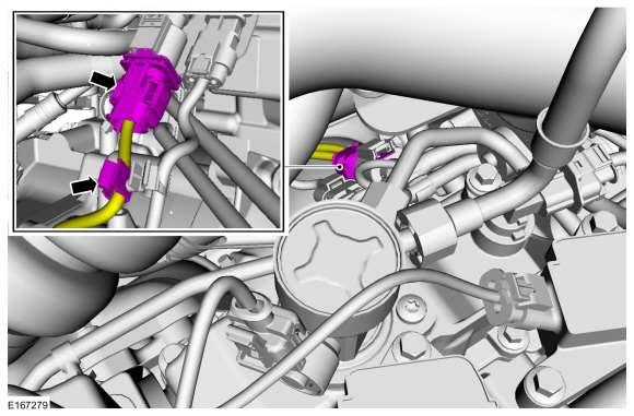
Disconnect the HO2S electrical connector and detach the wiring harness retainer.
 |
-
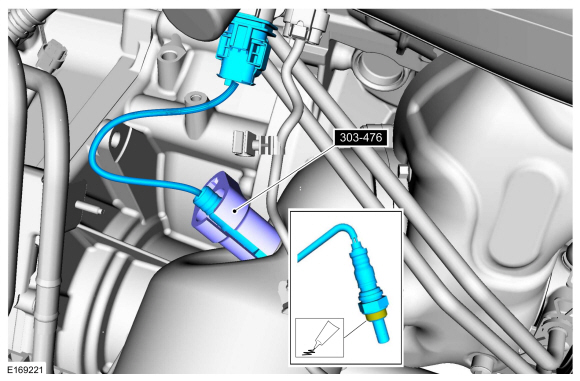
Remove the HO2S.
Use Special Service Tool: 303-476 (T94P-9472-A) Socket, Exhaust Gas Oxygen Sensor.
Material: Motorcraft® Penetrating and Lock Lubricant / XL-1
 |
Installation
-
Calculate the correct torque wrench setting for the
following torque. Refer to Torque Wrench Adapter Formula in the Apex.
Install the HO2S.
Use Special Service Tool: 303-476 (T94P-9472-A) Socket, Exhaust Gas Oxygen Sensor.
Material: Motorcraft® High Temperature Nickel Anti-Seize Lubricant / XL-2
Torque: 35 lb.ft (48 Nm)
 |
-
Connect the HO2S electrical connector and attach the wiring harness retainer.
 |
-
Install the air cleaner outlet pipe.
Refer to: Air Cleaner Outlet Pipe (303-12A Intake Air Distribution and Filtering - 1.5L EcoBoost (118kW/160PS) – I4, Removal and Installation).
-
Install the engine appearance cover.
 |
 Fuel Rail Pressure (FRP) Sensor. Removal and Installation
Materials
Name
Specification
Engine Oil - SAE 5W-20 - Synthetic Blend Motor OilXO-5W20-Q1SP
WSS-M2C945-B1
Removal
NOTE:
Removal steps in this procedure may contain installation details...
 Intake Air Temperature (IAT) Sensor. Removal and Installation
Removal
NOTE:
Removal steps in this procedure may contain installation details.
Disconnect the IAT sensor electrical connector and remove the IAT sensor...
Other information:
Ford Fusion 2013–2020 Service Manual: Rear Door Speaker. Removal and Installation
Removal NOTE: Removal steps in this procedure may contain installation details. Remove the rear door trim panel. Refer to: Rear Door Trim Panel (501-05 Interior Trim and Ornamentation, Removal and Installation). Remove the bolts and the door midwoofer speaker...
Ford Fusion 2013–2020 Service Manual: Front Suspension Height Sensor. Removal and Installation
Removal NOTE: Removal steps in this procedure may contain installation details. With the vehicle in NEUTRAL, position it on a hoist. Refer to: Jacking and Lifting - Overview (100-02 Jacking and Lifting, Description and Operation). NOTE: RH height sensor assembly shown, LH similar...
Categories
- Manuals Home
- 2nd Generation Ford Fusion Owners Manual
- 2nd Generation Ford Fusion Service Manual
- Electrical
- Starter Motor. Removal and Installation
- Intake Manifold. Removal and Installation
- New on site
- Most important about car
Manual Climate Control

Note: Depending on your vehicle option package, the controls may look different from what you see here.
Copyright © 2026 www.fofusion2.com