Ford Fusion: Interior Trim and Ornamentation / Headliner - Lowering. Removal and Installation
-
On both sides, remove the A-pillar trim panel.
Refer to: A-Pillar Trim Panel (501-05 Interior Trim and Ornamentation, Removal and Installation).
-
On both sides, remove the B-pillar trim panel.
Refer to: B-Pillar Trim Panel (501-05 Interior Trim and Ornamentation, Removal and Installation).
-
On both sides, remove the C-pillar upper trim panels.
Refer to: C-Pillar Upper Trim Panel (501-05 Interior Trim and Ornamentation, Removal and Installation).
-
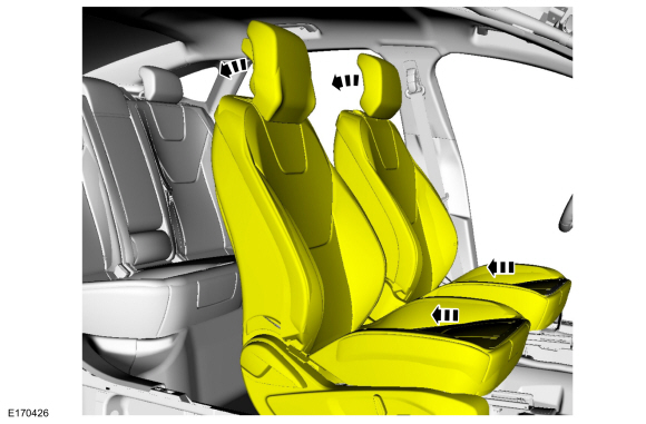
Position both front seats in the full rearward and full reclined position.
-
If equipped.
Remove the rear view mirror upper cover.
-
If equipped.
Remove the rear view mirror lower cover.
-
If equipped.
Disconnect the electrical connectors.
-
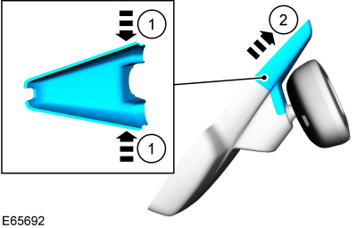
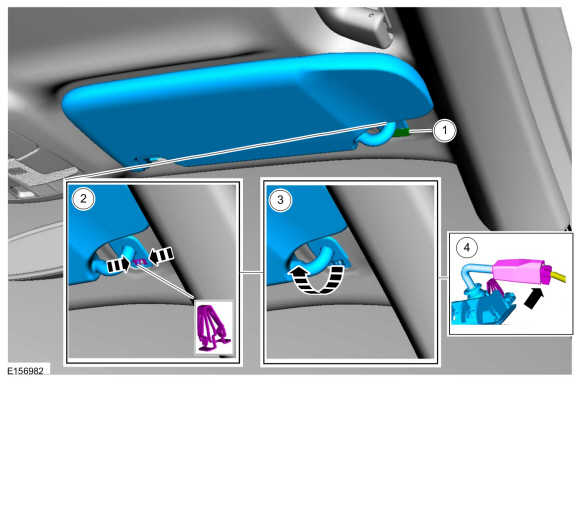
NOTE:
RH side shown, LH side similar.
On both sides.
Remove the sun visor.
-
Remove the retainer cap.
-
Release the retainer.
-
Remove the sun visor.
-
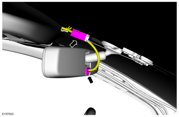
If equipped.
Disconnect the electrical connector.
-
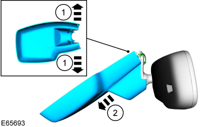
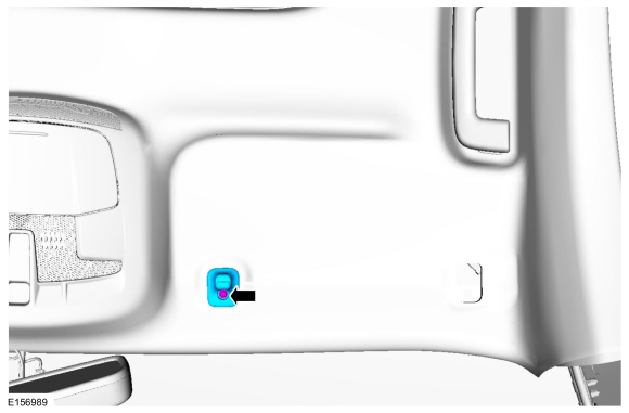
NOTE:
RH side shown, LH side similar.
On both sides.
Remove the retainer and the sun visor clip.
-
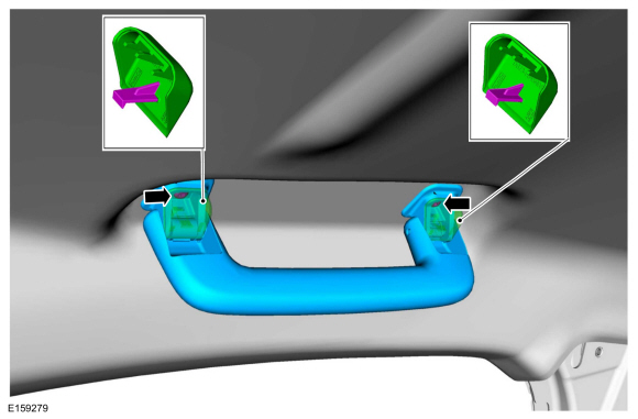
All.
Remove the retainer covers and the retainers and remove the assist handles.
-
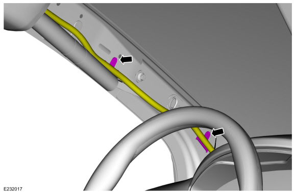
On LH side, release the retainers and position aside the wire harness.
-
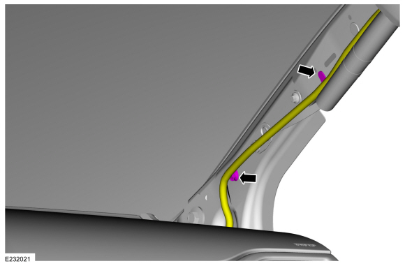
If equipped.
On the RH side, release the retainers and position aside the headliner wire harness.
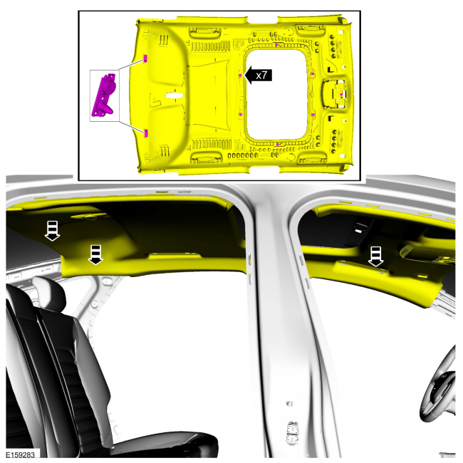
-
Release the magnets and locator pins and magnets and lower the headliner.
Materials
Name
Specification
3M™ Super-Fast Repair Adhesive04747
-
Removal
NOTICE:
Use care to not crease the headliner during removal and installation or damage to the headliner can occur...
Removal
NOTE:
Removal steps in this procedure may contain installation details.
WARNING:
Before beginning any service procedure in this
section, refer to Safety Warnings in section 100-00 General Information...
Other information:
DTC Chart: Instrument Panel Cluster (IPC)
Diagnostics in this manual assume a certain skill level and knowledge of Ford-specific diagnostic practices. REFER to: Diagnostic Methods (100-00 General Information, Description and Operation).
DTC Chart - IPC
DTC
Description
Action
P0460:11
Fuel Level Sensor "A" Circuit: Circuit Sh..
Special Tool(s) /
General Equipment
307-636Alignment Pins- Valve BodyTKIT-2008ET-FLMTKIT-2008ET-ROW
Removal
Remove the main control cover.
Refer to: Main Control Cover - 1.5L EcoBoost (118kW/160PS) – I4 (307-01A Automatic Transmission - 6-Speed Automatic Transmission – 6F35, Removal and Installation).
Refer to: Main Control Cover - 2.5L Duratec (125kW/170PS) (307-01..
 Headliner. Removal and Installation
 Parcel Shelf. Removal and Installation