Ford Fusion: Exterior Lighting / Headlamp Assembly. Removal and Installation
Ford Fusion 2013–2020 Service Manual / Electrical / Lighting / Exterior Lighting / Headlamp Assembly. Removal and Installation
Removal
NOTE: The procedure for the LH headlamp assembly is shown, the RH headlamp assembly is similar.
NOTE: Removal steps in this procedure may contain installation details.
-
Remove the front bumper cover.
Refer to: Front Bumper Cover (501-19 Bumpers, Removal and Installation).
-
-
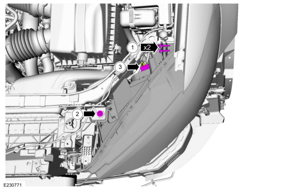
Remove the bolts.
-
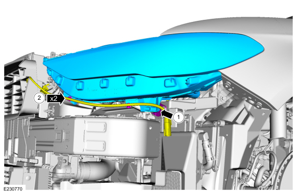
Remove the bolt.
-
Disconnect the electrical connector.
-
Remove the bolts.
 |
-
Remove the headlamp assembly.
-
Separate the headlamp assembly from the ball stud.
-
If equipped, separate the wiring harness guides from the headlamp assembly.
-
Separate the headlamp assembly from the ball stud.
 |
Installation
-
Position the headlamp assembly.
-
Install the headlamp assembly on the ball stud.
-
If equipped, install the wiring harness guides to the headlamp assembly.
-
Install the headlamp assembly on the ball stud.
 |
-
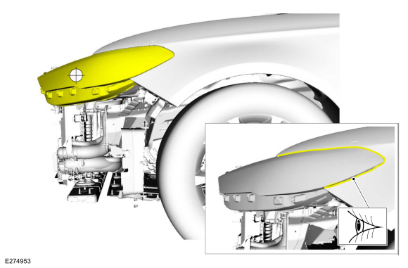
NOTE: When installing a new headlamp assembly, position the headlamp ballstud in the socket and align the headlamp assembly edge to the fender. If the headlamp assembly cannot be aligned adjust the ballstud socket.
Install the headlamp assembly
-
Install the bolts finger tight.
-
Install the screw finger tight.
-
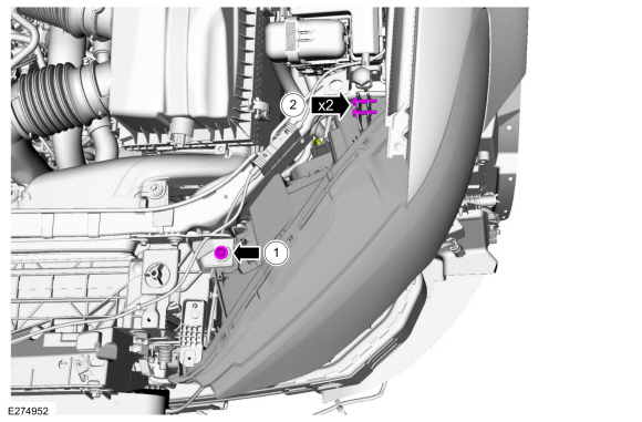
Connect the electrical connector.
-
Install the bolts finger tight.
 |
-
Align the headlamp assembly to the fender opening.
 |
-
-
Tighten the bolt.
-
Tighten the screws.
Torque: 32 lb.in (3.6 Nm)
-
Tighten the bolt.
 |
-
Install the bumper cover.
Refer to: Front Bumper Cover (501-19 Bumpers, Removal and Installation).
-
Adjust the headlamp.
Refer to: Headlamp Adjustment (417-01 Exterior Lighting, General Procedures).
 Hazard Flasher Switch. Removal and Installation
Removal
NOTE:
Removal steps in this procedure may contain installation details.
Using a non-marring tool release and position the hazard flasher switch...
 Headlamp Bulb. Removal and Installation
Removal
NOTE:
The procedure for the LH headlamp assembly is shown, the RH headlamp assembly is similar.
NOTE:
Removal steps in this procedure may contain installation details...
Other information:
Ford Fusion 2013–2020 Service Manual: In-Vehicle Temperature and Humidity Sensor. Removal and Installation
Removal NOTE: Removal steps in this procedure may contain installation details. WARNING: Before beginning any service procedure in this section, refer to Safety Warnings in section 100-00 General Information. Failure to follow this instruction may result in serious personal injury...
Ford Fusion 2013–2020 Service Manual: Turbine Shaft Speed (TSS) Sensor. Removal and Installation
Removal Remove the air cleaner. Refer to: Air Cleaner (303-12A Intake Air Distribution and Filtering - 1.5L EcoBoost (118kW/160PS) – I4, Removal and Installation). Refer to: Air Cleaner (303-12B Intake Air Distribution and Filtering - 2.0L EcoBoost (184kW/250PS) – MI4, Removal and Installation)...
Categories
- Manuals Home
- 2nd Generation Ford Fusion Owners Manual
- 2nd Generation Ford Fusion Service Manual
- Starter Motor. Removal and Installation
- Garage Door Opener
- Pre-Collision Assist (IF EQUIPPED)
- New on site
- Most important about car
Adjusting the Steering Wheel
WARNING: Do not adjust the steering wheel when your vehicle is moving.
Note: Make sure that you are sitting in the correct position.
Copyright © 2026 www.fofusion2.com