Ford Fusion: Front Seats / Front Seat. Removal and Installation
Removal
 WARNING:
The following procedure describes critical repair steps
required for correct seat component installation. Follow all notes and
steps carefully. Do not place any objects between the seat components
and the body of the vehicle, nor any objects within a joint internal to
the seat structure. Failure to follow step instructions may result in
incorrect operation of the seat components and increases the risk of
serious personal injury.
WARNING:
The following procedure describes critical repair steps
required for correct seat component installation. Follow all notes and
steps carefully. Do not place any objects between the seat components
and the body of the vehicle, nor any objects within a joint internal to
the seat structure. Failure to follow step instructions may result in
incorrect operation of the seat components and increases the risk of
serious personal injury.
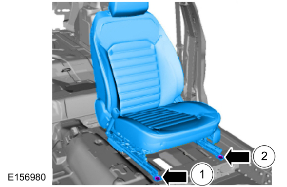
NOTE: Driver seat shown, passenger seat similar.
-
Turn the ignition OFF and wait at least one minute. WARNING:
Turn the ignition OFF and wait one minute to deplete
the backup power supply. Ignition must remain OFF until repair is
complete. Failure to follow this instruction may result in serious
personal injury or death in the event of an accidental deployment.
WARNING:
Turn the ignition OFF and wait one minute to deplete
the backup power supply. Ignition must remain OFF until repair is
complete. Failure to follow this instruction may result in serious
personal injury or death in the event of an accidental deployment.
-
-
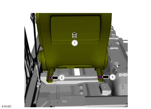
Position the seat frontward to access the seat rear bolts.
-
Remove the seat bolt.
-
Remove the seat bolt.
-
Position the seat frontward to access the seat rear bolts.
 |
-
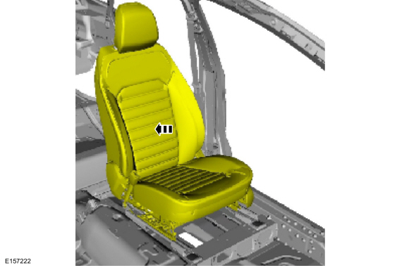
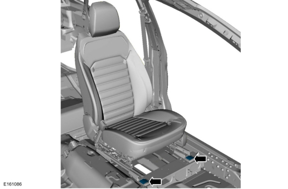
Move the front seat to the full rearward position.
 |
-
If a seat side airbag SRS fault is present, depower the SRS.
Refer to: Supplemental Restraint System (SRS) Depowering and Repowering (501-20B Supplemental Restraint System, General Procedures).
-
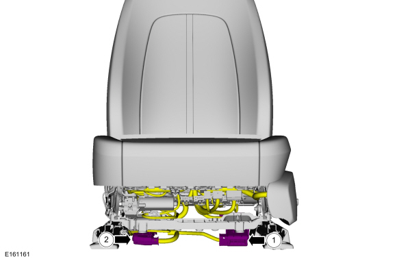
Remove the front seat bolt caps.
 |
-
Remove the front seat bolts.
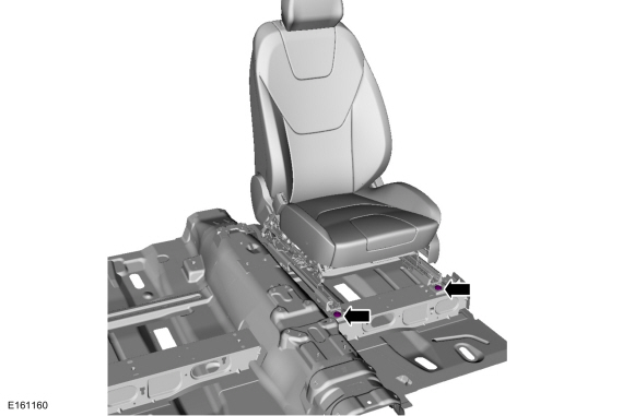 |
-
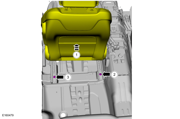
Remove the front seat.
-
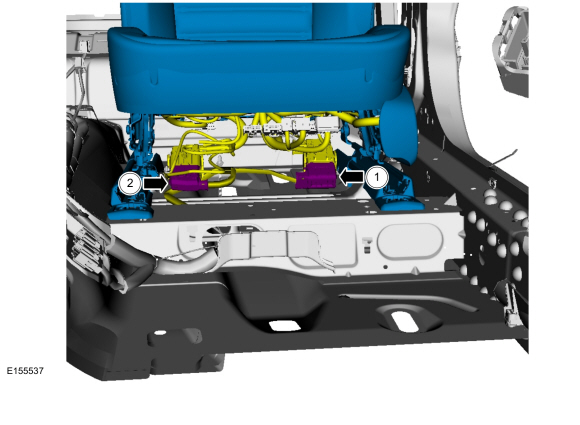
Disconnect the wiring harness electrical connector.
-
If equipped.
Disconnect the heated seat electrical connector.
-
Disconnect the wiring harness electrical connector.
 |
Installation
-
Install the front seat and tighten the bolts in the sequence shown.
Torque: 35 lb.ft (47.5 Nm)
 |
-
Install the front seat bolt caps.
 |
-
-
Connect the wiring harness electrical connector.
-
If equipped.
Connect the heated seat wiring harness electrical connector.
-
Connect the wiring harness electrical connector.
 |
-
If the SRS has been depowered, repower the SRS.
Refer to: Supplemental Restraint System (SRS) Depowering and Repowering (501-20B Supplemental Restraint System, General Procedures).
-
Position the seat forward to access the seat rear bolts and tighten the bolts in the sequence shown.
Torque: 35 lb.ft (47.5 Nm)
 |
 Front Head Restraint Guide Sleeve. Removal and Installation
Special Tool(s) /
General Equipment
Flat Headed Screw Driver
Removal
Vehicles without police seats
Depress the locking tabs...
 Front Seat Backrest. Removal and Installation
Removal
WARNING:
The following procedure describes critical repair steps
required for correct seat component installation. Follow all notes and
steps carefully...
Other information:
Ford Fusion 2013–2020 Service Manual: Gateway Module A (GWM). Removal and Installation
Removal NOTE: Removal steps in this procedure may contain installation details. NOTE: If installing a new module, it is necessary to upload the module configuration information to the scan tool prior to removing the module. This information must be downloaded into the new module after installation...
Ford Fusion 2013–2020 Service Manual: Transmission Fluid Level Check. General Procedures
Materials Name Specification Motorcraft® MERCON® LV Automatic Transmission FluidXT-10-QLVC WSS-M2C938-AMERCON® LV, Check Connect the diagnostic scan tool to the vehicle. Monitor the TFT PID. With the engine running in PARK on a level surface make sure the transmission is at normal operating temperature 85-93° C (185-200° F)...
Categories
- Manuals Home
- 2nd Generation Ford Fusion Owners Manual
- 2nd Generation Ford Fusion Service Manual
- Body Control Module (BCM). Removal and Installation
- Electronic Parking Brake (EPB) Service Mode Activation and Deactivation. General Procedures
- Transmission - 1.5L EcoBoost (118kW/160PS) – I4. Removal and Installation
- New on site
- Most important about car
Child Safety Locks
When these locks are set, the rear doors cannot be opened from the inside.
