Ford Fusion: Front Seats / Front Seat Backrest. Removal and Installation
Ford Fusion 2013–2020 Service Manual / Body and Paint / Body and Paint / Front Seats / Front Seat Backrest. Removal and Installation
Removal
 WARNING:
The following procedure describes critical repair steps
required for correct seat component installation. Follow all notes and
steps carefully. Do not place any objects between the seat components
and the body of the vehicle, nor any objects within a joint internal to
the seat structure. Failure to follow step instructions may result in
incorrect operation of the seat components and increases the risk of
serious personal injury.
WARNING:
The following procedure describes critical repair steps
required for correct seat component installation. Follow all notes and
steps carefully. Do not place any objects between the seat components
and the body of the vehicle, nor any objects within a joint internal to
the seat structure. Failure to follow step instructions may result in
incorrect operation of the seat components and increases the risk of
serious personal injury.
NOTE: Removal steps in this procedure may contain installation details.
-
Remove the front seat.
Refer to: Front Seat (501-10A Front Seats, Removal and Installation).
-
-
If equipped.
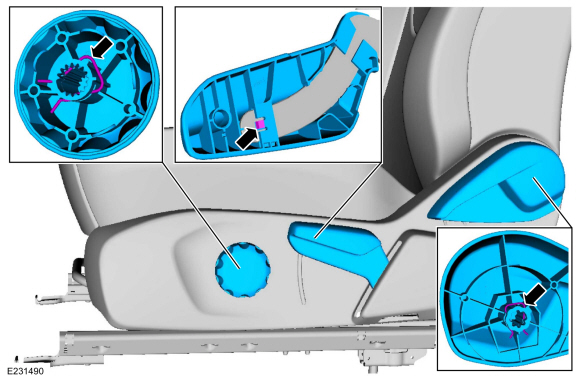
Release the lumbar knob retaining clip and remove the lumbar knob.
-
If equipped.
Release the height adjust handle locking tab and remove the height adjust handle.
-
If equipped.
Release the recline handle retaining clip and remove the recline handle.
-
If equipped.
 |
-
Remove the side shield screws.
 |
-
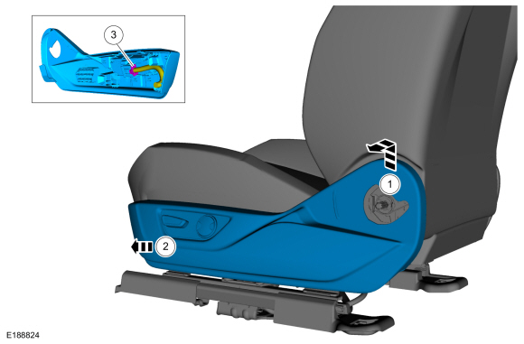
Remove the side shield.
-
Lift up on the rear of the side shield and pull outward.
-
Push the side shield forward.
-
If equipped.
Disconnect the electrical connector.
-
Lift up on the rear of the side shield and pull outward.
 |
-
If equipped.
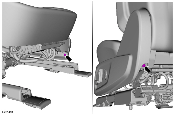
Position the manual lumbar assembly cable away from the seat track.
-
Disconnect the cable from the manual lumbar actuator.
-
Detach the cable retainers from the seat track.
-
Disconnect the cable from the manual lumbar actuator.
 |
-
Remove the screws and the recline cover.
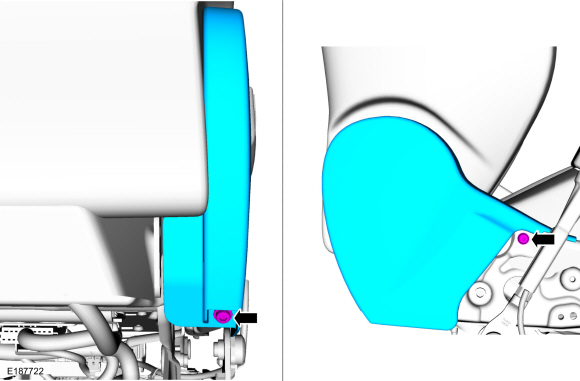 |
-
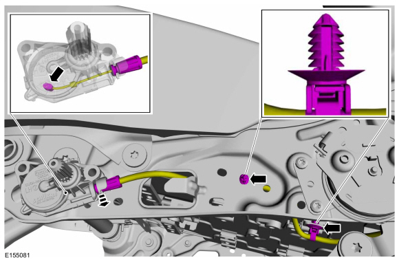
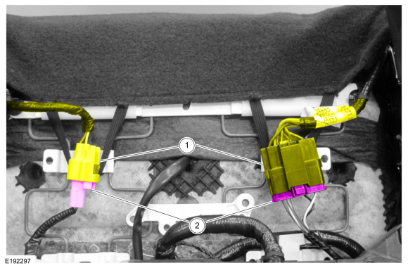
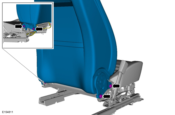
Position the backrest wire harness(es) aside.
-
Release the electrical connector retainer(s) from the seat track.
-
Release the locking tab(s) and disconnect the backrest wire harness electrical connector(s).
-
Release the electrical connector retainer(s) from the seat track.
 |
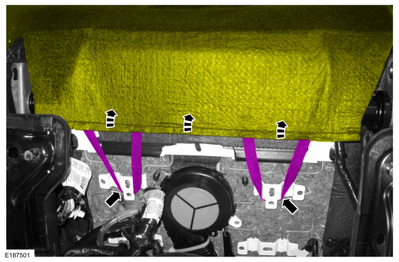
-
Detach the backrest cover straps and position the backrest cover upward.
 |
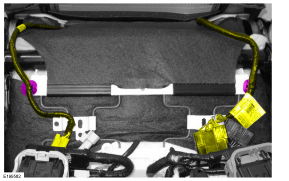
-
Release the wire harness retainers and position the wire harnesses aside.
 |
-
Remove the bolts and the front seat backrest.
Torque: 33 lb.ft (45 Nm)
 |
Installation
-
To install, reverse the removal procedure.
 Front Seat. Removal and Installation
Removal
WARNING:
The following procedure describes critical repair steps
required for correct seat component installation. Follow all notes and
steps carefully...
 Front Seat Backrest Blower Motor. Removal and Installation
Removal
Remove the front seat.
Refer to: Front Seat (501-10A Front Seats, Removal and Installation).
Detach the electrical connector retainers and position the wire harnesses aside...
Other information:
Ford Fusion 2013–2020 Service Manual: Glove Compartment. Removal and Installation
Special Tool(s) / General Equipment Interior Trim Remover Removal NOTE: Removal steps in this procedure may contain installation details. WARNING: Before beginning any service procedure in this section, refer to Safety Warnings in section 100-00 General Information...
Ford Fusion 2013–2020 Service Manual: Main Control Valve Body. Overhaul
Special Tool(s) / General Equipment 307-636Alignment Pins- Valve BodyTKIT-2008ET-FLMTKIT-2008ET-ROW Flat Headed Screw Driver Magnetic Socket Long Nose Pliers Main Control Valve Body and Solenoid Body Remove the solenoid body-to-valve body bolts and separate the solenoid body from the valve body...
Categories
- Manuals Home
- 2nd Generation Ford Fusion Owners Manual
- 2nd Generation Ford Fusion Service Manual
- Load Carrying
- Automatic Transmission Fluid Check - 1.5L EcoBoost™/2.0L EcoBoost™/2.5L. Automatic Transmission Fluid Check - 2.7L EcoBoost™
- Automatic Transmission - 6-Speed Automatic Transmission – 6F35
- New on site
- Most important about car
Manual Climate Control

Note: Depending on your vehicle option package, the controls may look different from what you see here.
Copyright © 2026 www.fofusion2.com