Ford Fusion: Front Seats / Front Seat Backrest Blower Motor. Removal and Installation
Ford Fusion 2013–2020 Service Manual / Body and Paint / Body and Paint / Front Seats / Front Seat Backrest Blower Motor. Removal and Installation
Removal
-
Remove the front seat.
Refer to: Front Seat (501-10A Front Seats, Removal and Installation).
-
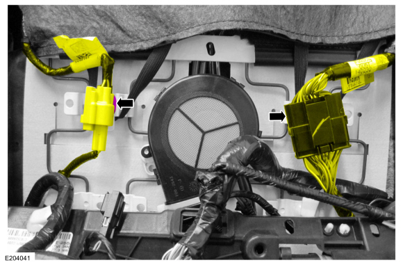
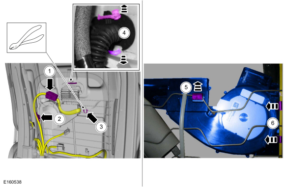
Detach the electrical connector retainers and position the wire harnesses aside.
 |
-
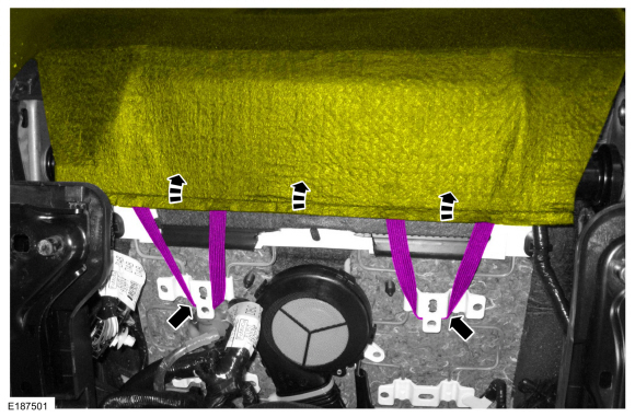
Detach the backrest cover straps and position the backrest cover upward.
 |
-
-
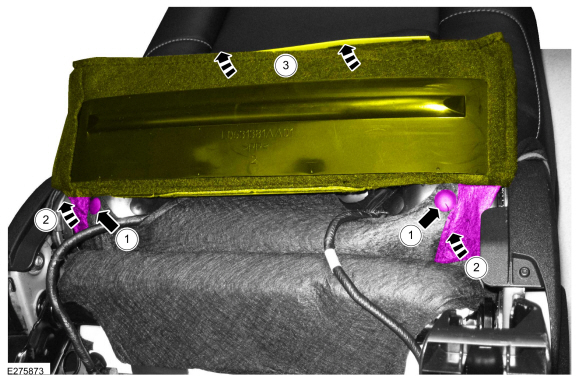
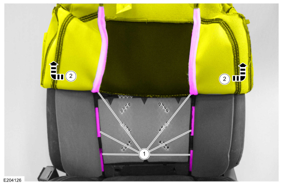
Remove the pin-type retainers.
-
Detach the hook-and-loop strips.
-
Lift the backrest cover flap.
-
Remove the pin-type retainers.
 |
-
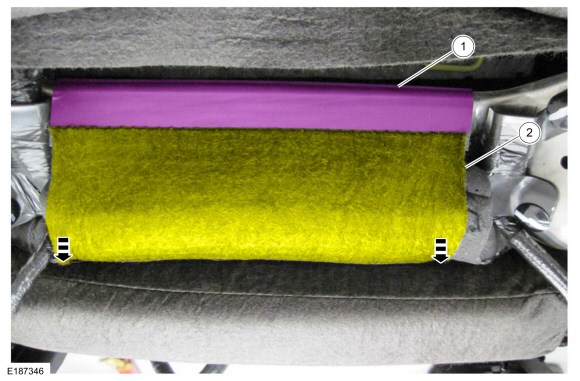
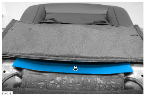
Position the front seat backrest cover.
-
Release the J-clip.
-
Position the backrest cover from between the seat cushion and backrest cushion.
-
Release the J-clip.
 |
-
Remove the backrest cover insert.
 |
-
NOTICE: Use care when separating the backrest trim cover from the hook-and-loop strips or the hook-and-loop strips may be torn from the backrest foam.
Partially invert the backrest cover enough to access the hog rings.
-
Release the hook-and-loop strips.
-
Invert the backrest cover.
-
Release the hook-and-loop strips.
 |
-
Remove the pin-type retainers from the deployment chute wrap and begin feeding it through the backrest foam.
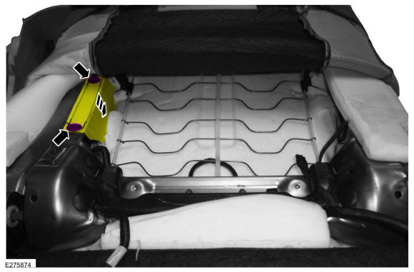 |
-
Pull the deployment chute wrap out of the backrest foam.
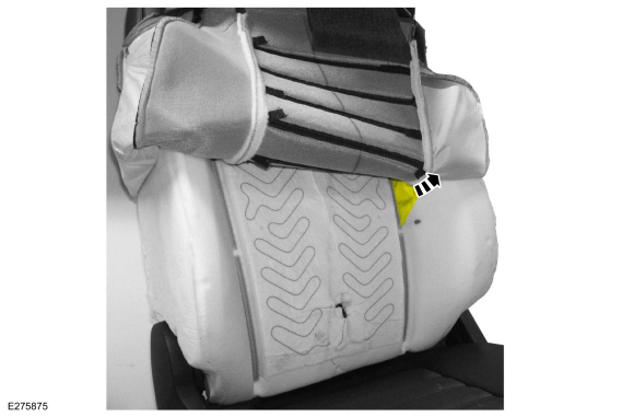 |
-
-
Disconnect the front seat backrest blower motor electrical connector.
-
Release the wire harness retainer.
-
Cut the tie strap.
-
Release the front seat backrest blower motor from the front seat backrest cushion.
-
Release the front seat backrest blower motor horizontal retainer.
-
Release the vertical retainers and remove the front seat backrest blower motor.
-
Disconnect the front seat backrest blower motor electrical connector.
 |
Installation
-
To install, reverse the removal procedure.
 Front Seat Backrest. Removal and Installation
Removal
WARNING:
The following procedure describes critical repair steps
required for correct seat component installation. Follow all notes and
steps carefully...
 Front Seat Backrest Cover. Removal and Installation
Removal
WARNING:
Front seat backrest trim covers installed on seats equipped
with seat side airbags cannot be repaired. A new trim cover must be
installed...
Other information:
Ford Fusion 2013–2020 Service Manual: Ignition Coil-On-Plug. Removal and Installation
Removal NOTE: Removal steps in this procedure may contain installation details. NOTE: Use compressed air to remove any foreign material from the ignition coil-on-plugs and surrounding area before removing the ignition coil-on-plugs. NOTE: When removing the ignition coil-on-plugs, a slight twisting motion will break the seal and ease removal...
Ford Fusion 2013–2020 Service Manual: Noise, Vibration and Harshness (NVH). Description and Operation
Acceptable Noise, Vibration and Harshness (NVH) Noise is any undesirable sound, usually unpleasant in nature. Vibration is any motion, shaking or trembling, that can be felt or seen when an object moves back and forth or up and down. Harshness is a ride quality issue where the vehicle's response to the road transmits sharply to the customer...
Categories
- Manuals Home
- 2nd Generation Ford Fusion Owners Manual
- 2nd Generation Ford Fusion Service Manual
- Transmission - 1.5L EcoBoost (118kW/160PS) – I4. Removal and Installation
- Body Control Module (BCM). Removal and Installation
- Memory Function
- New on site
- Most important about car
Direction Indicators. Interior Lamps
Direction Indicators

Push the lever up or down to use the direction indicators.
Copyright © 2026 www.fofusion2.com