Ford Fusion: Four-Wheel Drive Systems / Four-Wheel Drive Systems - System Operation and Component Description. Description and Operation
System Operation
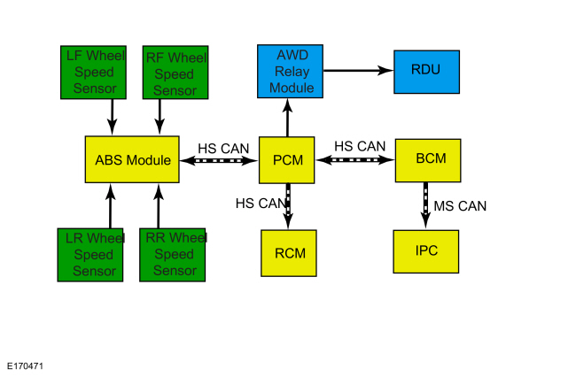
System Diagram
.jpg)
| Item | Description |
|---|---|
| 1 | PCM |
| 2 | HS-CAN |
| 3 | Active Torque Coupling (ATC) solenoid (integral to the Rear Drive Unit (RDU) |
| 4 | BCM |
| 5 | IPC |
| 6 | RCM |
| 7 | ABS module |
| 8 | HS-CAN |
| 9 | HS-CAN |
| 10 | MS-CAN |
| 11 | AWD relay module |
| 12 | LH rear wheel speed sensor |
| 13 | RH rear wheel speed sensor |
| 14 | RH front wheel speed sensor |
| 15 | LH front wheel speed sensor |
Network Message Chart
Module Network Input MessagesPCM
| Broadcast Message | Originating Module | Message Purpose |
|---|---|---|
| Vehicle yaw rate | RCM | The PCM uses lateral acceleration and yaw rate information for the four-wheel drive system to determine percentage of torque to be transferred to the rear wheels. |
| Wheel speed data | ABS module | The PCM uses wheel speed information for the four-wheel drive system to determine percentage of torque to be transferred to the rear wheels. |
| Accelerator pedal position | PCM | The PCM uses pedal information for the four-wheel drive system to determine percentage of torque to be transferred to the rear wheels. |
Spare Tire And Mismatched Tire Sizes
If the spare tire is installed, the AWD system may disable automatically and enter FWD only mode to protect driveline components. If the AWD systems detects 1 tire is 5% larger or smaller than the other tires, it may also disable the AWD system. This condition may be indicated by AWD OFF message in the message center. If there is a Check AWD message in the message center from using the spare tire, this indicator should turn off after reinstalling the repaired or replaced normal road tire and cycling the ignition OFF and ON. It is recommended to reinstall the repaired or replaced road tire as soon as possible. Major dissimilar tire sizes between the front and rear axles could cause the AWD system to stop functioning and default to FWD or damage the AWD system. If this condition occurs, a DTC is set and a Check AWD message is displayed on the message center.
AWD Control And Fault Indicators
The AWD system consists of a power transfer unit (PTU) case, driveshaft, front and rear halfshafts, AWD relay module, Rear Drive Unit (RDU) with integral Active Torque Coupling (ATC) solenoid, and includes the PCM for AWD control logic. Using inputs from various module/systems, the PCM sends a command to the AWD relay module which controls the amount of torque sent to the rear wheels by sending a PWM duty cycle to the Active Torque Coupling (ATC) solenoid. AWD system faults are be indicated by a driveline icon indicator in the IPC as well as the Check AWD message in the message center.
Heat Protection - Rear Drive Unit (RDU)
During aggressive on road driving, the AWD system may implement a heat protection mode to protect the AWD clutch from damage. Without power transfer unit (PTU) or Rear Drive Unit (RDU) temperature sensors, the PCM performs calculations to determine the need for the heat protection mode. If the AWD system detects an overheat condition, it enters a locked mode. If the heat in the Rear Drive Unit (RDU) continues to rise once in the locked mode, the PCM disables the Active Torque Coupling (ATC) solenoid. This condition may be indicated by an AWD Temporarily Disabled message in the message center. To resume normal operation, stop the vehicle in a safe location and turn the engine off for at least 10 minutes. After the engine is restarted and the AWD system has adequately cooled down, the AWD Temporarily Disabled message turns off and normal AWD operation returns. In the event the engine is not stopped, the AWD Temporarily Disabled message turns off when the system cools. Normal AWD operation returns once the message center displays AWD Restored.
Heat Protection - Power Transfer Unit (PTU)
During excessive use or trailer towing the AWD system may implement a heat protection mode to protect the PTU from damage. Without power transfer unit (PTU) temperature sensors, the PCM performs calculations to determine the need for the heat protection mode. The AWD system reduces commanded torque only to situation deemed critical for minimal function. Once the maximum temperature limit is reached, then FWD only is commanded. The PTU on vehicles equipped with the 6F50/55 transmission is equipped with a temperature sensor.
AWD Bar Code Identification
The AWD system on this vehicle uses a solenoid to control the Active Torque Coupling (ATC). Due to response rate differences within the AWD hardware, the PCM must know the response rate of the ATC. This can be done by programming the ATC bar code data into the PCM. The PCM uses this bar code information to match the clutch characteristics of the ATC solenoid with the desired output torque. If the bar code information does not match the PCM information, driveline damage or driveability concerns can occur. Therefore, if the PCM needs to be replaced, the new PCM needs to be configured with the existing ATC solenoid bar code information. If the rear drive axle need to be replaced, the existing PCM needs to be configured with the new ATC solenoid bar code information.
Automatic Torque Coupling Configuration Bar Code Label Location
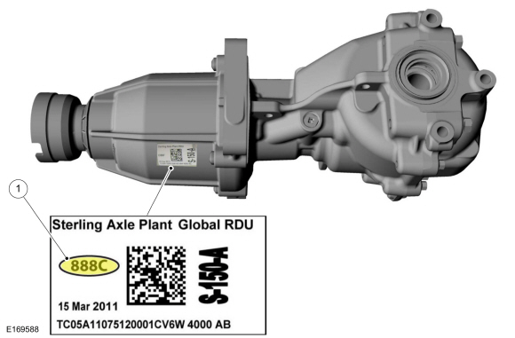
Label Location
| Item | Description |
| 1 | Active Torque Coupling (ATC) solenoid bar code label |
Automatic Torque Coupling Configuration
NOTICE: If the Active Torque Coupling (ATC) solenoid bar code information is not correct, Rear Drive Unit (RDU) damage or driveability concerns can occur.
NOTE: The 4-digit alpha numeric bar code is located on the label attached to the Rear Drive Unit (RDU).
Refer to: Active Torque Coupling Configuration (308-07A Four-Wheel Drive Systems, General Procedures).
AWD Drive Cycle
NOTE: Always drive the vehicle in a safe manner according to driving conditions and obey all traffic laws.
1. Carry out 3 accelerations from 0-30 mph (0-48 km/h) in a straight line.
- Perform this procedure at low, medium and full accelerator pedal position.
- Verify there is no perceived front wheel slip.
2. On dry pavement, drive the vehicle at 5 mph (8 km/h) in a fully locked turn.
- Verify there is no driveline binding.
Component Description
PCM
The PCM is the logic module for the four-wheel drive system. Multiple modules/system inputs are used for the four-wheel drive system to determine the percentage of torque to be transferred to the rear wheels.
Power Transfer Unit
The
power transfer unit (PTU) is a gearbox that attaches to the
transmission. The PTU directs power to the rear driveshaft and the Rear
Drive Unit (RDU). For more information on the PTU,
Refer to: Power Transfer Unit (308-07B Power Transfer Unit - 6-Speed Automatic Transmission – 6F35, Diagnosis and Testing).
Refer to: Power Transfer Unit (308-07C Power Transfer Unit - 6-Speed Automatic Transmission – 6F50/6F55, Diagnosis and Testing).
AWD Relay Module
The AWD relay module receives the command from the PCM, and in turn supplies a PWM output to the Automatic Torque Coupling (ATC) solenoid for the requested torque to be applied.
Automatic Torque Coupling (ATC) Solenoid
The
Automatic Torque Coupling (ATC) solenoid is integral to the Rear Drive
Unit (RDU), and applies clutch pressure as controlled by the AWD
relay module to increase or decrease torque to the rear wheels. The
Rear Drive Unit (RDU) transfers torque from the drive shaft to the rear
wheels depending on the specific request from the FWD system module ( PCM). The Rear Drive Unit (RDU) and Automatic Torque Coupling (ATC) solenoid are serviced in Chassis, Driveline section.
Refer to: Rear Drive Axle and Differential (205-02 Rear Drive Axle/Differential, Diagnosis and Testing).
 Four-Wheel Drive Systems - Overview. Description and Operation
The AWD system consists of the following:
Power transfer unit (PTU)
Front and rear halfshafts
Rear axle and driveshaft
AWD relay module
Rear axle with coupling device
Torque
from the engine is transferred through the transmission to the Power
Transfer Unit (PTU)...
 Four-Wheel Drive Systems. Diagnosis and Testing
DTC Chart: AWD System - PCM
Diagnostics in this manual assume a certain skill level and knowledge of Ford-specific diagnostic practices. REFER to: Diagnostic Methods (100-00 General Information, Description and Operation)...
Other information:
Ford Fusion 2013–2020 Service Manual: Flexplate. Removal and Installation
Special Tool(s) / General Equipment 303-103 (T74P-6375-A) Holding Tool, FlywheelT74P-77000-ATKIT-2009TC-F Removal Remove the transmission. Refer to: Transmission - 1.5L EcoBoost (118kW/160PS) – I4 (307-01A Automatic Transmission - 6-Speed Automatic Transmission – 6F35, Removal and Installation)...
Ford Fusion 2013–2020 Service Manual: All-Wheel Drive (AWD) Module. Removal and Installation
Removal Release the clips and remove the loadspace trim panel. Disconnect the AWD module electrical connector. Remove the AWD module push pin fasteners and the AWD module. Installation Install the AWD module and the push pin fasteners...
Categories
- Manuals Home
- 2nd Generation Ford Fusion Owners Manual
- 2nd Generation Ford Fusion Service Manual
- Traction Control
- Pre-Collision Assist (IF EQUIPPED)
- Garage Door Opener
- New on site
- Most important about car
Parallel Parking
The system detects available parallel parking spaces and steers your vehicle into the space. You control the accelerator, gearshift and brakes. The system visually and audibly guides you into a parallel parking space.
 Press the button once to search
for a parking space.
Press the button once to search
for a parking space.