Ford Fusion: Four-Wheel Drive Systems / Four-Wheel Drive Systems. Diagnosis and Testing
DTC Chart: AWD System - PCM
Diagnostics in this manual assume a certain skill level and knowledge of Ford-specific diagnostic practices.
REFER to: Diagnostic Methods (100-00 General Information, Description and Operation).
Network DTCs
(U-codes) are often a result of intermittent concerns such as damaged
wiring or low battery voltage occurrences. Additionally, vehicle repair
procedures, such as module reprogramming, often set network DTCs. Replacing a module to resolve a network DTC is unlikely to resolve the concern. To prevent repeat network DTC concerns, inspect all network wiring, especially connectors. Test the vehicle battery.
REFER to: Battery (414-01 Battery, Mounting and Cables, Diagnosis and Testing).
DTC Chart - PCM
| DTC | Description | Action |
| P164D | AWD ID Block Corrupted, Not Programmed |
PROGRAM the PCM with the Active Torque Coupling (ATC) solenoid bar code information using Automatic Torque Coupling Configuration. REFER to: Four-Wheel Drive Systems - System Operation and Component Description (308-07A Four-Wheel Drive Systems, Description and Operation). |
| P181F | Clutch Control System Performance |
This is an internal AWD relay module fault. INSTALL a new AWD relay module. REFER to: All-Wheel Drive (AWD) Module (308-07A Four-Wheel Drive Systems, Removal and Installation). |
| P182B | Transfer Case Fluid Temperature Sensor Circuit Range/Performance | GO to Pinpoint Test F |
| P182C | Transfer Case Fluid Temperature Sensor Circuit Low | GO to Pinpoint Test F |
| P182D | Transfer Case Fluid Temperature Sensor Circuit High | GO to Pinpoint Test F |
| P183D | Transfer Case Fluid Over Temperature | GO to Pinpoint Test F |
| P187B | Tire Size Out of Acceptable Range - AWD Disabled / Limited Function | GO to Pinpoint Test B |
| P188B | AWD Clutch Control Circuit | GO to Pinpoint Test C |
| P188C | AWD Relay Module Communication Circuit | CLEAR the DTCs. REPEAT the self-test. If the DTC returns, GO to Pinpoint Test D |
| P188D | AWD Relay Module Feedback Circuit | CLEAR the DTCs. REPEAT the self-test. If the DTC returns, GO to Pinpoint Test D |
Symptom Chart
Diagnostics in this manual assume a certain skill level and knowledge of Ford-specific diagnostic practices.
REFER to: Diagnostic Methods (100-00 General Information, Description and Operation).
In most circumstances, the PCM sets DTCs to help guide with diagnostics. Refer to the DTC Chart before using the symptom chart. The Symptom column lists the vehicle condition. The Possible Sources column lists a detailed vehicle condition. The Action column lists the action to be performed to determine the cause of the condition. Each action lists the components that can cause the system and the individual components in that system. The components are listed in order of disassembly. Use the list of components and the required action to focus on disassembly inspections for the root cause of the concern.
Symptom Chart - Four-Wheel Drive Systems
| Condition | Possible Sources | Actions |
|---|---|---|
| Unable to duplicate customer concern; no DTC present | The concern description is inaccurate | CARRY OUT the AWD System Functional Test. GO to Pinpoint Test A |
| Vehicle has no or inadequate torque at rear wheels |
|
GO to Pinpoint Test C |
| Wheels/tires |
Check wheels and tires for damage. REFER to: Wheels and Tires (204-04A Wheels and Tires, Diagnosis and Testing). |
|
| Rear axle |
Check rear axle for damage. REFER to: Rear Drive Axle and Differential (205-02 Rear Drive Axle/Differential, Diagnosis and Testing). |
|
| PTU mechanical failure |
Check PTU for damage. REFER to: Rear Drive Axle and Differential (205-02 Rear Drive Axle/Differential, Diagnosis and Testing). |
|
| Vehicle binds in a turn or resists turning/pulsates or shudders in a straight line | Wheels/tires |
Check wheels and tires for damage. REFER to: Wheels and Tires (204-04A Wheels and Tires, Diagnosis and Testing). |
| Wiring, terminals or connectors | GO to Pinpoint Test E | |
| Driveshaft |
Check driveshaft for damage. REFER to: Driveshaft (205-01 Driveshaft, Diagnosis and Testing). |
|
|
GO to Pinpoint Test E | |
| PTU mechanical failure |
Check PTU for damage. REFER to: Power Transfer Unit (308-07B Power Transfer Unit - 6-Speed Automatic Transmission – 6F35, Diagnosis and Testing). REFER to: Power Transfer Unit (308-07C Power Transfer Unit - 6-Speed Automatic Transmission – 6F50/6F55, Diagnosis and Testing). |
|
| Driveshaft |
Check driveshaft for damage. REFER to: Suspension System (204-00 Suspension System - General Information, Diagnosis and Testing). |
|
| Wheel bearings |
Check wheel bearings for damage. REFER to: Suspension System (204-00 Suspension System - General Information, Diagnosis and Testing). |
|
| ABS |
CHECK the ABS. REFER to: Anti-Lock Brake System (ABS) and Stability Control (206-09 Anti-Lock Brake System (ABS) and Stability Control, Diagnosis and Testing). |
|
| Halfshafts |
Check the halfshafts for damage. REFER to: Rear Drive Halfshafts (205-05 Rear Drive Halfshafts, Diagnosis and Testing). |
|
| Tire/axle out of acceptable range |
|
GO to Pinpoint Test B |
Pinpoint Tests
AWD System Functional Test
Normal Operation and Fault Conditions
The AWD system is an active system, which means it not only responds to wheel slip between the front and rear axles but also has the ability to anticipate wheel slip and transfer torque to the rear wheels before the slip occurs. The AWD system is active all the time and requires no input from the operator. The AWD system continuously monitors vehicle conditions and automatically adjusts the torque distribution between the front and rear wheels. During normal operation, most of the torque is delivered to the front wheels. If wheel slip between the front and rear wheels is detected, if the vehicle is under acceleration or if the vehicle is in a handling event, the AWD system increases and distributes torque to the rear wheels as needed. When the AWD system is functioning properly, there should be no perceived speed difference between the front and rear axles when launching or driving the vehicle on any uniform surface. Traction should be similar to a part time 4WD system in 4H (4X4 HIGH), but have no binding in turns.
The AWD_CLTCH_CMD PID percentage displayed on the scan tool is an inverse value. 95% = Clutch is released, 5% = Clutch fully applied.
NOTE: 0% is an invalid command. A DTC may set if 0% is commanded using output state control.
Visual Inspection and Diagnostic Pre-checks
- ABS sensor wiring
- Constant velocity joints
- Driveshaft
- Halfshafts
- Tire size
- Tire wear
- U-joints
PINPOINT TEST A : AWD (ALL-WHEEL DRIVE) SYSTEM FUNCTIONAL TEST
 WARNING:
When directed to drive the vehicle as part of this test,
drive the vehicle on a hard surface in an area without traffic to
prevent a crash. Failure to follow these instructions may result in
personal injury.
WARNING:
When directed to drive the vehicle as part of this test,
drive the vehicle on a hard surface in an area without traffic to
prevent a crash. Failure to follow these instructions may result in
personal injury.
|
||||
| NOTE: Check related modules for Diagnostic Trouble Codes (DTCs). If Diagnostic Trouble Codes (DTCs) are set in other modules, diagnose those Diagnostic Trouble Codes (DTCs) first before continuing. | ||||
| A1 CHECK FOR ACTIVE TORQUE COUPLING SOLENOID LOCK | ||||
Is driveline wind-up present in turns?
|
||||
| A2 CHECK ABS WHEEL SPEEDS | ||||
Are all 4 wheel speeds within 1.2 mph ( 2 km/h) of each other?
|
||||
| A3 CHECK VEHICLE ACCELERATION IN A STRAIGHT LINE | ||||
Does the vehicle pulsate or shudder while accelerating?
|
||||
| A4 CHECK VEHICLE TURNING ABILITY | ||||
Does the vehicle bind in the turn or resist turning?
|
||||
| A5 CHECK TORQUE AT THE REAR WHEELS | ||||
Does the vehicle bind in the turn or resist turning?
|
DTC P187B
Normal Operation and Fault Conditions
The AWD system uses input data from the ABS module wheel speed sensor inputs to the PCM. A dissimilar spare tire size (other than the spare tire provided) or major dissimilar tire sizes or improperly inflated tires between the front and rear axles could cause the AWD system to stop functioning correctly.
DTC Fault Trigger Conditions
| DTC | Description | Fault Trigger Conditions |
|---|---|---|
| P187B | Tire Size Out of Acceptable Range - AWD Disabled/Limited Function | When the PCM detects an inappropriate size wheels/tires (greater than 5% difference in size across the front and rear axle or greater than 14% difference in size at one wheel on either the front or rear axle) installed. |
Possible Causes
- Wiring, terminals or connectors
- Wheels/tires
- ABS system
Visual Inspection and Diagnostic Pre-checks
- Inspect for correct tire size and inflation.
 WARNING:
When directed to drive the vehicle as part of this test,
drive the vehicle on a hard surface in an area without traffic to
prevent a crash. Failure to follow these instructions may result in
personal injury.
WARNING:
When directed to drive the vehicle as part of this test,
drive the vehicle on a hard surface in an area without traffic to
prevent a crash. Failure to follow these instructions may result in
personal injury.
PINPOINT TEST B : DTC P187B
| B1 CHECK FOR RECENT DIFFERENT SIZED TIRE USAGE | ||||
Was a tire recently installed on the vehicle that was not originally supplied with the vehicle or has the mini spare been used?
|
||||
| B2 CHECK TIRE SIZE AND BRAND | ||||
Are all 4 tires the same size and brand?
|
||||
| B3 CHECK TIRE AIR PRESSURES | ||||
Are all 4 tires at the recommended air pressure?
|
||||
| B4 CHECK ABS WHEEL SPEEDS | ||||
Are all 4 wheel speeds within 1.2 mph ( 2 km/h) of each other?
|
||||
| B5 CHECK FOR CORRECT ABS AND AWD (ALL-WHEEL DRIVE) SYSTEM OPERATION | ||||
Is the concern still present?
|
 Click here to access Guided Routine (ABS).
 Internet Explorer version 11 or greater is required to perform this Pinpoint Test.
DTC P188B
Refer to Wiring Diagrams Cell 34 for schematic and connector information.
Normal Operation and Fault Conditions
The AWD system uses data from other systems as inputs to the PCM. The PCM uses the inputs to determine the appropriate time to send a signal and have the AWD relay module energize the Active Torque Coupling (ATC) solenoid.
The AWD_CLTCH_CMD PID percentage displayed on the scan tool is an inverse value. 95% = Clutch is released, 5% = Clutch fully applied.
NOTE: 0% is an invalid command. A DTC may set if 0% is commanded using output state control.
DTC Fault Trigger Conditions
| DTC | Description | Fault Trigger Conditions |
|---|---|---|
| P188B | AWD Clutch Control Circuit | When the PCM detects an open, a short to ground or voltage on the Active Torque Coupling (ATC) solenoid voltage supply and/or return circuit. |
Possible Causes
- Wiring, terminals or connectors
- Active Torque Coupling (ATC) solenoid (part of the Rear Drive Unit (RDU))
- AWD relay module
- PCM
Visual Inspection and Diagnostic Pre-checks
- Active torque coupling (ATC) solenoid harness
PINPOINT TEST C : P188B
| C1 CHECK THE ACTIVE TORQUE COUPLING SOLENOID | |||||||||||||
Is the resistance between 1 and 3 ohms?
|
|||||||||||||
| C2 CHECK THE ACTIVE TORQUE COUPLING SOLENOID CIRCUITS FOR A SHORT TO VOLTAGE | |||||||||||||
Is any voltage present?
|
|||||||||||||
| C3 CHECK THE ACTIVE TORQUE COUPLING SOLENOID CIRCUITS FOR A SHORT TO GROUND | |||||||||||||
Is the resistance greater than 10,000 ohms?
|
|||||||||||||
| C4 CHECK THE ACTIVE TORQUE COUPLING SOLENOID CIRCUITS FOR AN OPEN | |||||||||||||
Is the resistance less than 3 ohms?
|
|||||||||||||
| C5 CHECK THE ACTIVE TORQUE COUPLING SOLENOID CIRCUITS FOR A SHORT TOGETHER | |||||||||||||
Is the resistance greater than 10,000 ohms?
|
|||||||||||||
| C6 CHECK FOR CORRECT PCM (POWERTRAIN CONTROL MODULE) OPERATION | |||||||||||||
Is the concern still present?
|
 C4347-1

 C4347-2


 Click here to access Guided Routine (PCM).
 Internet Explorer version 11 or greater is required to perform this Pinpoint Test.
DTCs P188C, P188D
Refer to Wiring Diagrams Cell 34 for schematic and connector information.
Normal Operation and Fault Conditions
The AWD system uses data from other systems as inputs to the PCM. The PCM uses the inputs to determine the appropriate time to send a signal and have the AWD relay module energize the Active Torque Coupling (ATC) solenoid.
DTC Fault Trigger Conditions
| DTC | Description | Fault Trigger Conditions |
|---|---|---|
| P188C | AWD Relay Module Communication Circuit | When the PCM detects an open, a short to ground or voltage on the command circuit. |
| P188D | AWD Relay Module Feedback Circuit | When the PCM detects an open, a short to ground or voltage on the feedback circuit. |
Possible Causes
- Wiring, terminals or connectors
- AWD relay module
- PCM
Visual Inspection and Diagnostic Pre-checks
- BJB fuse 12 (15A)
PINPOINT TEST D : AWD (ALL-WHEEL DRIVE) INFORMATION CIRCUITS FAULT
| D1 CHECK THE AWD (ALL-WHEEL DRIVE) RELAY VOLTAGE CIRCUIT | ||||||||||||||||||||||||||||||||||||||||
|
NOTE: Fuse 12 (15A) protects multiple components. Check related systems that may be inoperative.
Is the voltage greater than 11 volts?
|
||||||||||||||||||||||||||||||||||||||||
| D2 CHECK THE AWD (ALL-WHEEL DRIVE) RELAY MODULE GROUND CIRCUIT FOR AN OPEN | ||||||||||||||||||||||||||||||||||||||||
Is the voltage greater than 11 volts?
|
||||||||||||||||||||||||||||||||||||||||
| D3 CHECK THE AWD (ALL-WHEEL DRIVE) RELAY MODULE COMMAND AND FEEDBACK CIRCUITS FOR A SHORT TO VOLTAGE | ||||||||||||||||||||||||||||||||||||||||
Is any voltage present?
|
||||||||||||||||||||||||||||||||||||||||
| D4 CHECK THE AWD (ALL-WHEEL DRIVE) RELAY MODULE COMMAND AND FEEDBACK CIRCUITS FOR A SHORT TO GROUND | ||||||||||||||||||||||||||||||||||||||||
Is the resistance greater than 10,000 ohms?
|
||||||||||||||||||||||||||||||||||||||||
| D5 CHECK THE AWD (ALL-WHEEL DRIVE) RELAY MODULE COMMAND AND FEEDBACK CIRCUITS FOR AN OPEN | ||||||||||||||||||||||||||||||||||||||||
Is the resistance less than 3 ohms?
|
||||||||||||||||||||||||||||||||||||||||
| D6 CHECK THE AWD (ALL-WHEEL DRIVE) RELAY MODULE COMMAND AND FEEDBACK CIRCUITS FOR A SHORT TOGETHER | ||||||||||||||||||||||||||||||||||||||||
Is the resistance greater than 10,000 ohms?
|
||||||||||||||||||||||||||||||||||||||||
| D7 CHECK FOR CORRECT PCM (POWERTRAIN CONTROL MODULE) OPERATION | ||||||||||||||||||||||||||||||||||||||||
Is the concern still present?
|


 Click here to access Guided Routine (PCM).
 Internet Explorer version 11 or greater is required to perform this Pinpoint Test.
 Click here to access Guided Routine (PCM).
 Internet Explorer version 11 or greater is required to perform this Pinpoint Test.
Vehicle Binds in a Turn or Resists Turning/Pulsates or Shudders in a Straight Line
Refer to Wiring Diagrams Cell 34 for schematic and connector information.
Normal Operation and Fault Conditions
The AWD system is an active system, which means it not only responds to wheel slip between the front and rear axles but also has the ability to anticipate wheel slip and transfer torque to the rear wheels before the slip occurs. The AWD system is active all the time and requires no input from the operator. The AWD system continuously monitors vehicle conditions and automatically adjusts the torque distribution between the front and rear wheels. During normal operation, most of the torque is delivered to the front wheels. If wheel slip between the front and rear wheels is detected, if the vehicle is under acceleration or if the vehicle is in a handling event, the AWD system increases and distributes torque to the rear wheels as needed. When the AWD system is functioning properly, there should be no perceived speed difference between the front and rear axles when launching or driving the vehicle on any uniform surface. Traction should be similar to a part time 4WD system in 4H (4X4 HIGH), but have no binding in turns.
The AWD_CLTCH_CMD PID percentage displayed on the scan tool is an inverse value. 95% = Clutch is released, 5% = Clutch fully applied.
NOTE: 0% is an invalid command. A DTC may set if 0% is commanded using output state control.
Possible Causes
- Wiring, terminals and connectors
- Wheels/tires
- ABS system
- AWD relay module
- Active Torque Coupling (ATC) Clutch
Visual Inspection and Diagnostic Pre-checks
- Wheel speed sensor wiring harness
 WARNING:
When directed to drive the vehicle as part of this test,
drive the vehicle on a hard surface in an area without traffic to
prevent a crash. Failure to follow these instructions may result in
personal injury.
WARNING:
When directed to drive the vehicle as part of this test,
drive the vehicle on a hard surface in an area without traffic to
prevent a crash. Failure to follow these instructions may result in
personal injury.
PINPOINT TEST E : VEHICLE BINDS IN A TURN OR RESISTS TURNING/PULSATES OR SHUDDERS IN A STRAIGHT LINE
| E1 CHECK FOR TORQUE AT THE REAR WHEELS | ||||
Is a pulsation or shudder still present?
|
||||
| E2 MONITOR THE CLUTCH STATUS PID | ||||
Is the duty cycle less than 80%?
|
||||
| E3 CHECK FOR THE CORRECT WHEEL SPEEDS | ||||
Are all 4 wheel speeds within 1.2 mph ( 2 km/h) of each other?
|
||||
| E4 CHECK FOR CORRECT AWD (ALL-WHEEL DRIVE) RELAY MODULE OPERATION | ||||
Is the concern still present?
|
P182B, P182C, P182D, P183D
Refer to Wiring Diagrams Cell 34 for schematic and connector information.
Normal Operation and Fault Conditions
This power transfer unit (PTU) fluid temperature sensor is located in the (PTU) (6F50/55 only). It is a temperature-sensitive device called a thermistor. The resistance value of the sensor varies with temperature change. The PCM monitors the voltage across the transfer case fluid temperature sensor to determine the temperature of the power transfer unit (PTU) fluid temperature.
The AWD_CLTCH_CMD PID percentage displayed on the scan tool is an inverse value. 95% = Clutch is released, 5% = Clutch fully applied.
NOTE: 0% is an invalid command. A DTC may set if 0% is commanded using output state control.
DTC Fault Trigger Conditions
| DTC | Description | Fault Trigger Conditions |
|---|---|---|
| P182B | Transfer Case Fluid Temperature Sensor Circuit Range/Performance | This DTC sets when the PCM detects an open, a short to ground or voltage on the sensor circuit. |
| P182C | Transfer Case Fluid Temperature Sensor Circuit Low | This DTC sets when the PCM detects a short to ground an open, or low voltage on the sensor circuit. |
| P182D | Transfer Case Fluid Temperature Sensor Circuit High | This DTC sets when the PCM detects the sensor circuit voltage is high. |
| P183D | Transfer Case Fluid Over Temperature | This DTC sets in the PCM when the PTU fluid temperature has exceeded it's maximum operating temperature. |
Possible Causes
- Wiring, terminals and connectors
- Transfer case fluid temperature sensor (Power Transfer unit Sensor)
- PCM
Visual Inspection and Diagnostic Pre-checks
- Transfer case fluid temperature sensor wiring harness
- PTU operation is normal and quiet
- PTU fluid level
PINPOINT TEST F : P182B, P182C, P182D, P183D
| F1 RETRIEVE AND RECORD ALL DTCS | ||||||||||||||||||||||||||||||||||||||||||||||||||||||||||||||||||||||||||||||||||||||||||||||||||||||||||||||||||||||||||||||||||||||||||||||
Is DTC P182B, P182C, P182D, and/or P183D present?
|
||||||||||||||||||||||||||||||||||||||||||||||||||||||||||||||||||||||||||||||||||||||||||||||||||||||||||||||||||||||||||||||||||||||||||||||
| F2 CHECK THE TRANSFER CASE FLUID TEMPERATURE SENSOR SIGNAL VOLTAGE | ||||||||||||||||||||||||||||||||||||||||||||||||||||||||||||||||||||||||||||||||||||||||||||||||||||||||||||||||||||||||||||||||||||||||||||||
Is the voltage greater than 4.1 volts?
|
||||||||||||||||||||||||||||||||||||||||||||||||||||||||||||||||||||||||||||||||||||||||||||||||||||||||||||||||||||||||||||||||||||||||||||||
| F3 CHECK THE TRANSFER CASE FLUID TEMPERATURE SENSOR GROUND CIRCUIT FOR AN OPEN | ||||||||||||||||||||||||||||||||||||||||||||||||||||||||||||||||||||||||||||||||||||||||||||||||||||||||||||||||||||||||||||||||||||||||||||||
Is the voltage greater than 4.1 volts?
|
||||||||||||||||||||||||||||||||||||||||||||||||||||||||||||||||||||||||||||||||||||||||||||||||||||||||||||||||||||||||||||||||||||||||||||||
| F4 CHECK THE TRANSFER CASE FLUID TEMPERATURE SENSOR SIGNAL CIRCUIT FOR AN OPEN | ||||||||||||||||||||||||||||||||||||||||||||||||||||||||||||||||||||||||||||||||||||||||||||||||||||||||||||||||||||||||||||||||||||||||||||||
Is the resistance less than 3 ohms?
|
||||||||||||||||||||||||||||||||||||||||||||||||||||||||||||||||||||||||||||||||||||||||||||||||||||||||||||||||||||||||||||||||||||||||||||||
| F5 CHECK THE TRANSFER CASE FLUID TEMPERATURE SENSOR SIGNAL CIRCUIT FOR A SHORT TO GROUND | ||||||||||||||||||||||||||||||||||||||||||||||||||||||||||||||||||||||||||||||||||||||||||||||||||||||||||||||||||||||||||||||||||||||||||||||
Is the resistance greater than 10,000 ohms?
|
||||||||||||||||||||||||||||||||||||||||||||||||||||||||||||||||||||||||||||||||||||||||||||||||||||||||||||||||||||||||||||||||||||||||||||||
| F6 CHECK THE TRANSFER CASE FLUID TEMPERATURE SENSOR RESISTANCE | ||||||||||||||||||||||||||||||||||||||||||||||||||||||||||||||||||||||||||||||||||||||||||||||||||||||||||||||||||||||||||||||||||||||||||||||
Does the temperature to resistance specifications match?
|


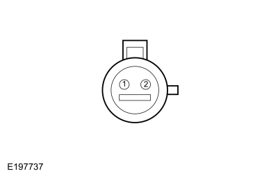
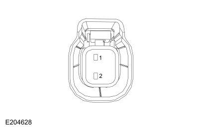 Transfer Case Fluid Temperature Sensor Component side, pin 1

 Transfer Case Fluid Temperature Sensor Component side, pin 2
 Click here to access Guided Routine (PCM).
 Internet Explorer version 11 or greater is required to perform this Pinpoint Test.
 Four-Wheel Drive Systems - System Operation and Component Description. Description and Operation
S..
 Active Torque Coupling Configuration. General Procedures
Configuration
NOTICE:
If the ATC (Active Torque Coupling) solenoid bar
code information is not correct, Rear Drive Unit (RDU) damage or
driveability concerns can occur...
Other information:
Ford Fusion 2013–2020 Owners Manual: Gauges
Type 1 and 2 Tachometer Information Display (Type 2 shown Type 1 similar) Speedometer Fuel Gauge Engine Coolant Temperature Gauge Information Display Odometer Located in the bottom of the information display. Registers the accumulated distance your vehicle has traveled...
Ford Fusion 2013–2020 Service Manual: Oil Pan. Removal and Installation
Special Tool(s) / General Equipment Strap Wrench Oil Drain Equipment Materials Name Specification Motorcraft® High Performance Engine RTV SiliconeTA-357 WSE-M4G323-A6 Engine Oil - SAE 5W-20 - Synthetic Blend Motor OilXO-5W20-Q1SP WSS-M2C945-B1 Removal With the vehicle in NEUTRAL, position it on a hoist...
Categories
- Manuals Home
- 2nd Generation Ford Fusion Owners Manual
- 2nd Generation Ford Fusion Service Manual
- Garage Door Opener
- Load Carrying
- Under Hood Overview - 1.5L EcoBoost™, 2.0L EcoBoost™, 2.5L, 2.7L EcoBoost™
- New on site
- Most important about car
Child Safety Locks
When these locks are set, the rear doors cannot be opened from the inside.
