Ford Fusion: Brake System - General Information / Component Bleeding. General Procedures
Ford Fusion 2013–2020 Service Manual / Chassis / Brake System / Brake System - General Information / Component Bleeding. General Procedures
Special Tool(s) / General Equipment
| Master Cylinder Bleeding Set |
Bleeding
NOTICE: If the fluid is spilled on the paintwork, the affected area must be immediately washed down with cold water.
Master Cylinder
NOTE: When a new brake master cylinder has been installed, it should be primed to prevent air from entering the system.
-
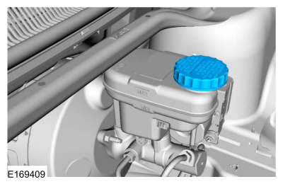
NOTE: Make sure the area around the master cylinder cap is clean and free of foreign material.
Remove the brake fluid reservoir cap.
 |
-
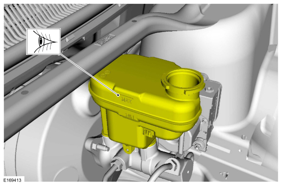
Fill the reservoir with clean, specified brake fluid.
Refer to: Specifications (206-00 Brake System - General Information, Specifications).
 |
-
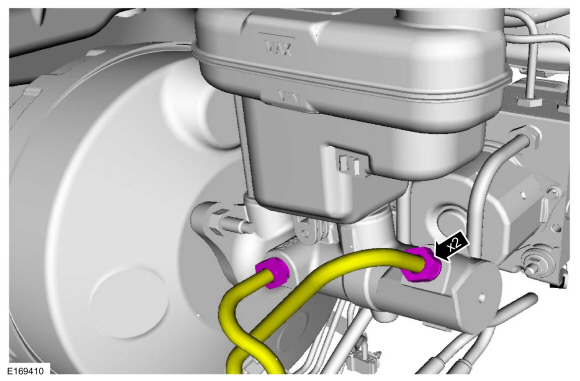
Loosen and remove the brake tube fittings.
 |
-
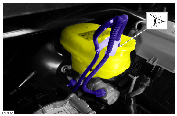
Install the master cylinder bleeding set.
Use the General Equipment: Master Cylinder Bleeding Set
 |
-
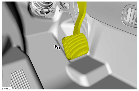
Have an assistant pump the brake pedal slowly until clear bubble free fluid flows from the brake tubes.
 |
-
Remove the master cylinder bleeding set.
Remove the General Equipment: Master Cylinder Bleeding Set
 |
-
Tighten the brake tube fittings.
Refer to: Specifications (206-00 Brake System - General Information, Specifications).
 |
-
Fill the reservoir with clean, specified brake fluid.
Refer to: Specifications (206-00 Brake System - General Information, Specifications).
 |
-
Refer to: Brake System Pressure Bleeding (206-00 Brake System - General Information, General Procedures).
Brake Caliper, Wheel Cylinder, Brake Hose or Brake Tube
-
NOTE: Pressure bleeding the brake system is required anytime a hydraulic brake system component has been disconnected.
Refer to: Brake System Pressure Bleeding (206-00 Brake System - General Information, General Procedures).
 Brake System Pressure Bleeding. General Procedures
Special Tool(s) /
General Equipment
Brake/Clutch System Pressure Bleeder/Filler
Fluid Container
Bleeding
All vehicles
NOTICE:
If the fluid is spilled on the paintwork, the affected area must be immediately washed down with cold water...

Other information:
Ford Fusion 2013–2020 Service Manual: Fuel Filler Door. Removal and Installation
Removal Open the fuel filler door. Using a screwdriver, pry the retaining tab back and slide the fuel filler door from the fuel filler door hinge. Installation To install, reverse the removal procedure. ..
Ford Fusion 2013–2020 Service Manual: Refrigerant Identification Testing - Vehicles With: R1234YF Refrigerant. General Procedures
Special Tool(s) / General Equipment Refrigerant Identification Equipment Activation NOTE: Use Refrigerant Identification Equipment to identify gas samples taken directly from the refrigeration system or storage containers prior to recovering or charging the refrigerant system. NOTE: Use Refrigerant Identification Equipment that conforms to SAE J2912 standard for R-1234yf..
Categories
- Manuals Home
- 2nd Generation Ford Fusion Owners Manual
- 2nd Generation Ford Fusion Service Manual
- Garage Door Opener
- Powertrain
- Body Control Module (BCM). Removal and Installation
- New on site
- Most important about car
Power Door Locks
The power door lock control is on the driver and front passenger door panels.
Copyright © 2026 www.fofusion2.com