Ford Fusion: Climate Control System - General Information / Cabin Heater Coolant Pump - 1.5L EcoBoost (118kW/160PS) – I4. Removal and Installation
Ford Fusion 2013–2020 Service Manual / Electrical / Climate Control System / Climate Control System - General Information / Cabin Heater Coolant Pump - 1.5L EcoBoost (118kW/160PS) – I4. Removal and Installation
Special Tool(s) / General Equipment
| Hose Clamp(s) | |
| Hose Clamp Remover/Installer |
Removal
NOTE: Removal steps in this procedure may contain installation details.
-
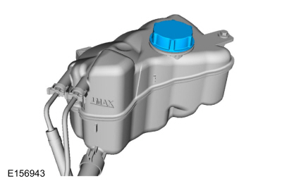
Release the pressure in the cooling system by slowly turning the pressure relief cap one-half turn counterclockwise. When the pressure is released, remove the pressure relief cap. WARNING:
When releasing the cooling system pressure, cover the coolant expansion tank cap with a thick cloth.
WARNING:
When releasing the cooling system pressure, cover the coolant expansion tank cap with a thick cloth.
 |
-
With the vehicle in N, position it on a hoist.
Refer to: Jacking and Lifting - Overview (100-02 Jacking and Lifting, Description and Operation).
-
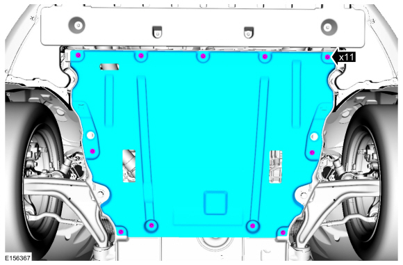
Remove the retainers and the engine undershield.
 |
-
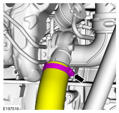
Loosen the clamp and position the CAC tube aside.
Torque: 44 lb.in (5 Nm)
 |
-
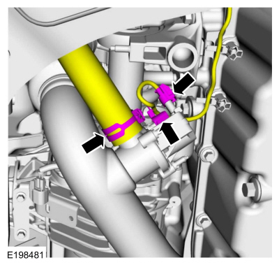
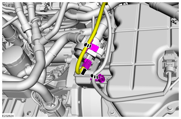
Disconnect the bypass hose, electrical connector and the wire retainer.
Use the General Equipment: Hose Clamp Remover/Installer
 |
-
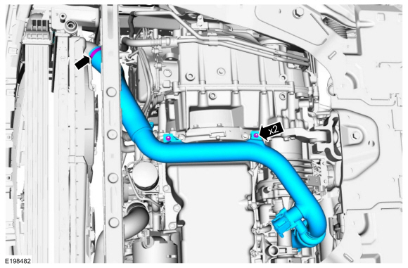
Loosen the clamp, remove the nuts and the CAC tube.
Torque:
Nuts: 97 lb.in (11 Nm)
Clamp: 44 lb.in (5 Nm)
 |
-
Detach the wire harness retainers and disconnect the electrical connector.
 |
-
-
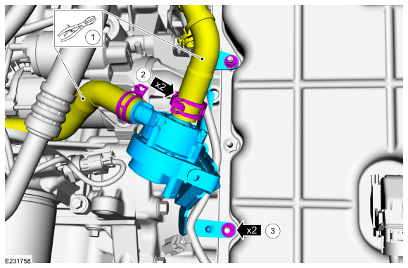
Install hose clamping pliers on the heater hoses.
Use the General Equipment: Hose Clamp(s)
-
Release the clamps, disconnect the heater inlet and outlet hoses.
-
Remove the nuts and the cabin heater coolant pump.
Torque: 89 lb.in (10 Nm)
-
Install hose clamping pliers on the heater hoses.
 |
Installation
-
To install, reverse the removal procedure.
-
Fill and bleed the cooling system.
Refer to: Engine Cooling System Draining, Vacuum Filling and Bleeding (303-03A Engine Cooling - 1.5L EcoBoost (118kW/160PS) – I4, General Procedures).
 Cabin Air Filter. Removal and Installation
Removal
NOTE:
Removal steps in this procedure may contain installation details.
WARNING:
Before beginning any service procedure in this
section, refer to Safety Warnings in section 100-00 General Information...
 Center Registers. Removal and Installation
Removal
NOTE:
Removal steps in this procedure may contain installation details.
WARNING:
Before beginning any service procedure in this
section, refer to Safety Warnings in section 100-00 General Information...
Other information:
Ford Fusion 2013–2020 Service Manual: Boost Pressure Sensor. Removal and Installation
Removal NOTE: Removal steps in this procedure may contain installation details. Disconnect the electrical connector, remove the retainer and the turbocharger boost pressure sensor. Torque: 89 lb.in (10 Nm) Installation To install, reverse the removal procedure...
Ford Fusion 2013–2020 Service Manual: Four-Wheel Drive Systems. Diagnosis and Testing
DTC Chart: AWD System - PCM Diagnostics in this manual assume a certain skill level and knowledge of Ford-specific diagnostic practices. REFER to: Diagnostic Methods (100-00 General Information, Description and Operation). Network DTCs (U-codes) are often a result of intermittent concerns such as damaged wiring or low battery voltage occurrences...
Categories
- Manuals Home
- 2nd Generation Ford Fusion Owners Manual
- 2nd Generation Ford Fusion Service Manual
- Automatic Transmission - 6-Speed Automatic Transmission – 6F35
- Under Hood Overview - 1.5L EcoBoost™, 2.0L EcoBoost™, 2.5L, 2.7L EcoBoost™
- Load Carrying
- New on site
- Most important about car
Direction Indicators. Interior Lamps
Direction Indicators

Push the lever up or down to use the direction indicators.
Copyright © 2024 www.fofusion2.com