Ford Fusion: Body Repairs - Vehicle Specific Information and Tolerance Checks / Body and Frame. Description and Operation
Body
 WARNING:
Electric vehicles damaged by a crash may have compromised
high voltage safety systems and present a potential high voltage
electrical shock hazard. Exercise caution and wear appropriate Personal
Protective Equipment (PPE) safety gear, including high voltage safety
gloves and boots. Remove all metallic jewelry, including watches and
rings. Isolate the HV system as directed by the Ford Emergency Response
Guide for the vehicle. Failure to follow these instructions may result
in serious personal injury or death.
WARNING:
Electric vehicles damaged by a crash may have compromised
high voltage safety systems and present a potential high voltage
electrical shock hazard. Exercise caution and wear appropriate Personal
Protective Equipment (PPE) safety gear, including high voltage safety
gloves and boots. Remove all metallic jewelry, including watches and
rings. Isolate the HV system as directed by the Ford Emergency Response
Guide for the vehicle. Failure to follow these instructions may result
in serious personal injury or death.
 WARNING:
Never install used or reconditioned parts (as specified
below) from pre-owned, salvaged or damaged vehicles. The use of such
parts could lead to serious injury. Never use non-Ford parts or
accessories for completing repairs. Ford Motor Company does not approve
or recognize body and structural repair procedures, tools, parts or
anything but new genuine Ford equipment. Ford cannot attest to the
safety, quality, durability or legality of non-Ford parts or
accessories. Use of such parts could lead to serious personal injury as
they may contain damage which is not visible. Ford does not approve use
of the following: Salvaged or used parts Major body clips or assemblies
from salvage vehicles Aftermarket structural or body components Salvaged
or reconditioned wheels Used Supplemental Restraint System (SRS)
components air bags restraint system modules safety belts, buckles or
retractors crash sensors Returning a vehicle to pre-accident condition
can only be assured if repair procedures are carried out by skilled
technicians using new genuine Ford parts and Ford-approved methods.
Structural component repair procedures approved by Ford, using genuine
Ford parts, have been validated by Ford Motor Company engineers. Ford
Motor Company does not endorse, cannot attest to, and makes no
representations regarding structural repairs (frames, rails, aprons and
body panels) carried out using non-genuine Ford Motor Company parts or
non-Ford-approved methods. In particular, Ford makes no representations
that the vehicle will meet any crash safety or anti-corrosion
performance requirement. Such parts and methods have not been tested by
Ford, and may not meet Ford's requirements for safety, performance,
strength, quality, durability and corrosion protection. Ford Motor
Company bears no responsibility or liability of any kind if repairs are
performed using alternative structural component repair procedures
and/or parts.
WARNING:
Never install used or reconditioned parts (as specified
below) from pre-owned, salvaged or damaged vehicles. The use of such
parts could lead to serious injury. Never use non-Ford parts or
accessories for completing repairs. Ford Motor Company does not approve
or recognize body and structural repair procedures, tools, parts or
anything but new genuine Ford equipment. Ford cannot attest to the
safety, quality, durability or legality of non-Ford parts or
accessories. Use of such parts could lead to serious personal injury as
they may contain damage which is not visible. Ford does not approve use
of the following: Salvaged or used parts Major body clips or assemblies
from salvage vehicles Aftermarket structural or body components Salvaged
or reconditioned wheels Used Supplemental Restraint System (SRS)
components air bags restraint system modules safety belts, buckles or
retractors crash sensors Returning a vehicle to pre-accident condition
can only be assured if repair procedures are carried out by skilled
technicians using new genuine Ford parts and Ford-approved methods.
Structural component repair procedures approved by Ford, using genuine
Ford parts, have been validated by Ford Motor Company engineers. Ford
Motor Company does not endorse, cannot attest to, and makes no
representations regarding structural repairs (frames, rails, aprons and
body panels) carried out using non-genuine Ford Motor Company parts or
non-Ford-approved methods. In particular, Ford makes no representations
that the vehicle will meet any crash safety or anti-corrosion
performance requirement. Such parts and methods have not been tested by
Ford, and may not meet Ford's requirements for safety, performance,
strength, quality, durability and corrosion protection. Ford Motor
Company bears no responsibility or liability of any kind if repairs are
performed using alternative structural component repair procedures
and/or parts.
The body consists of the following:
- High-Strength Low Alloy (HSLA), high-strength, ultra high strength steel (UHSS) and mild steels
- Roof outer panel constructed of bake hardened (BH) steel
- Aluminum hood
- Steel luggage compartment lid
- Body side outer panels constructed of mild steel
- Dual Phase Steel (DP) in select body structure components
- Bolted, removable front fenders, hinged doors and hood
- Dent resistant steel fenders
- Front and rear subframe assemblies housing suspension and steering components
- Underbody components constructed of mild, dual-phase and high-strength steels
- Mastic pad material used on floor pan and roof panel for sound deadening
Body Dimensions
Body Margins - Front Panels
NOTE: All margins must be parallel within 1.0 mm unless otherwise noted for sheet metal-to-sheet metal interfaces only.
NOTE: Unless otherwise indicated, margin dimensions apply to RH and LH side of vehicle.
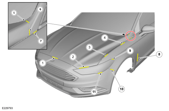
| Item | Description | Margin Specification | Flushness Specification |
|---|---|---|---|
| 1 | Hood-to-fascia | 3.5 mm ± 2.0 mm (Parallelism within 0.0 mm ± 2.0 mm) | 0.75 mm ± 2.2 mm |
| 2 | Headlamp-to-hood | 5.0 mm | 1.9 mm ± 2.2 mm |
| 3 | Hood-to-fender | 3.0 mm ± 1.7 mm | (Hood overflush to fender) 0.3 mm ± 1.8 mm |
| 4 | Hood-to-fender | 3.0 mm ± 1.7 mm | (Hood underflush to fender) 2.4 mm ± 1.8 mm |
| 5 | Hood-to-A-pillar | 4.1 mm ± 1.9 mm | 0.5 mm ± 1.8 mm |
| 6 | Hood-to-A-pillar | 3.2 mm ± 1.9 mm | 0.5 mm ± 2.4 mm |
| 7 | Fender-to-A-pillar | 3.0 mm ± 1.5 mm | — |
| 8 | Fender-to-front door | 3.4 mm ± 1.5 mm | 0.75 mm ± 1.5 mm |
| 9 | Headlamp-to-front fender | 2.0 mm ± 1.9 mm | 0.0 mm ± 2.0 mm |
| 10 | Fascia-to-fender | 0.0 mm ± 0.5 mm | 0.75 mm ± 1.5 mm |
| 11 | Headlamp-to-fascia | 2.0 mm ± 1.2 mm | — |
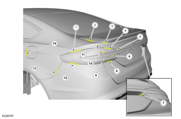
Body Margins - Fender Triangle
NOTE: All margins must be parallel within 1.0 mm unless otherwise noted for sheet metal-to-sheet metal interfaces only.
NOTE: Unless otherwise indicated, margin dimensions apply to RH and LH side of vehicle.
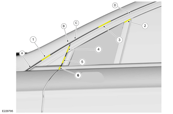
| Item | Description | Margin Specification | Flushness Specification |
|---|---|---|---|
| 1 | A-pillar-to-fender triangle | 2.0 mm (Margin varies 8.6 mm to 9.1 mm between point A and point B) | Flushness varies from 4.6 mm to 3.1 mm between point A and point B |
| 2 | Glass run-to-division bar | 0.7 mm ± 0.0 mm | — |
| 3 | A-pillar-to-glass run channel | 9.0 mm ± 2.7 mm | 2.7 mm (Flushness varies 3.1 mm to 1.3 mm between point C and point D) |
| 4 | Fender triangle-to-glass run channel | 3.0 mm ± 1.7 mm | 0.0 mm ± 2.7 mm |
| 5 | Fender triangle-to-fixed glass | 4.5 mm ± 2.7 mm | 1.5 mm ± 2.7 mm |
| 6 | Fender triangle-to-belt moulding | 4.5 mm ± 2.7 mm | 0.0 mm ± 2.7 mm |
Body Margins - Side Panels
NOTE: All margins must be parallel within 1.0 mm unless otherwise noted for sheet metal-to-sheet metal interfaces only.
NOTE: Unless otherwise indicated, margin dimensions apply to RH and LH side of vehicle.
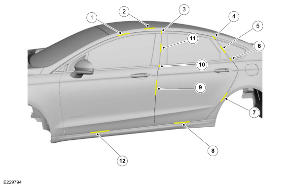
| Item | Description | Margin Specification | Flushness Specification |
|---|---|---|---|
| 1 | Front door-to-bodyside | 9.0 mm ± 2.7 mm | 1.0 mm ± 2.7 mm |
| 2 | Bodyside-to-roof | — | 6.0 mm (Reference) |
| 3 | Front door glass run-to-rear door glass run | 4.5 mm ± 2.7 mm | 0.0 mm ± 2.7 mm |
| 4 | Rear quarter glass moulding-to-rear glass run | 4.5 mm ± 2.7 mm | 0.0 mm ± 2.7 mm |
| 5 | Rear door C-pillar applique-to-quarter glass | 4.5 mm ± 2.7 mm | 5.0 mm ± 2.7 mm |
| 6 | Rear door belt moulding-to-rear quarter glass moulding | 4.5 mm ± 2.7 mm | 0.0 mm ± 2.7 mm |
| 7 | Rear door-to-bodyside quarter panel | 3.4 mm ± 1.5 mm | 0.0 mm ± 1.5 mm |
| 8 | Rear door-to-rocker moulding | 6.0 mm (Reference) | - 3.0 mm (Reference) |
| 9 | Front door-to-rear door | 3.4 mm ± 1.5 mm | 0.75 mm ± 1.5 mm |
| 10 | Front door belt moulding-to-rear door belt moulding | 4.5 mm ± 2.7 mm | 0.0 mm ± 2.7 mm |
| 11 | Front door applique-to-rear door applique | 4.5 mm ± 2.7 mm | 0.0 mm ± 2.7 mm |
| 12 | Front door-to-rocker moulding | 6.0 mm (Reference) | - 3.0 mm (Reference) |
Body Margins - Rear Panels
NOTE: All margins must be parallel within 1.0 mm unless otherwise noted for sheet metal-to-sheet metal interfaces only.
NOTE: Unless otherwise indicated, margin dimensions apply to RH and LH side of vehicle.
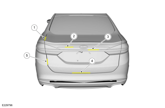
| Item | Description | Margin Specification | Flushness Specification |
|---|---|---|---|
| 1 | Bodyside-to-decklid | 3.0 mm ± 1.5 mm | 0.75 mm ± 2.0 mm |
| 2 | Luggage compartment lid-to-applique | 0.7 mm + 1.2 mm / -0.7 mm | 0.0 mm ± 1.4 mm |
| 3 | Rear closure applique-to-rear closure chrome applique | 1.0 mm ± 1.0 mm | 3.2 mm ± 1.4 mm |
| 4 | Luggage compartment lid-to-fascia | 6.0 mm ± 3.5 mm | — |
| 5 | Luggage compartment lid lower finish panel-to-fascia side | 5.0 mm ± 3.3 mm | 2.0 mm ± 3.5 mm |
Body Margins - Rear Spoiler and Lamps
NOTE: All margins must be parallel within 1.0 mm unless otherwise noted for sheet metal-to-sheet metal interfaces only.
NOTE: Unless otherwise indicated, margin dimensions apply to RH and LH side of vehicle.
| Item | Description | Margin Specification | Flushness Specification |
|---|---|---|---|
| 1 | Rear lamp-to-bodyside | 1.5 mm ± 1.2 mm | — |
| 2 | Spoiler-to-luggage compartment lid | 1.1 mm ± 1.0 mm | 2.5 mm ± 2.0 mm |
| 3 | Spoiler-to-luggage compartment lid | 0.5 mm | 3.2 mm ± 2.0 mm |
| 4 | Luggage compartment lid upper-to-luggage compartment lid lamp | 1.5 mm ± 1.2 mm | — |
| 5 | Rear closure chrome applique-to-luggage compartment lid lamp | 1.6 mm ± 1.6 mm | 0.0 mm ± 1.6 mm |
| 6 | Rear closure chrome applique-to-luggage compartment lid lamp | 1.0 mm ± 1.0 mm | — |
| 7 | Luggage compartment lid handle-to-luggage compartment lid lamp lens | 1.3 mm + 1.4 mm / - 1.3 mm | — |
| 8 | Luggage compartment lid lamp-to-luggage compartment lid lower finish panel | 2.0 mm ± 2.0 mm | — |
| 9 | Luggage compartment lid lamp-to-rear lamp | 3.5 mm ± 2.8 mm | 1.5 mm ± 2.7 mm (Luggage compartment lid lamp underflush) |
| 10 | Luggage compartment lid lamp-to-rear lamp | 3.5 mm ± 2.8 mm | 1.0 mm ± 2.7 mm |
| 11 | Bodyside lower-to-luggage compartment lid | 3.3 mm ± 1.5 mm | 1.0 mm ± 2.0 mm |
| 12 | Rear lamp-to-rear fascia | 2.0 mm ± 1.9 mm | — |
| 13 | Bodyside-to-rear fascia | 0.5 mm | 0.75 mm ± 1.5 mm |
| 14 | Fuel door-to-bodyside | 2.2 mm ± 1.2 mm | 1.0 mm ± 1.4 mm |
Under Hood Dimensions
NOTE: All measurements are on center unless otherwise indicated.
Front Door Opening Dimensions
NOTE: All measurements are on center unless otherwise indicated.
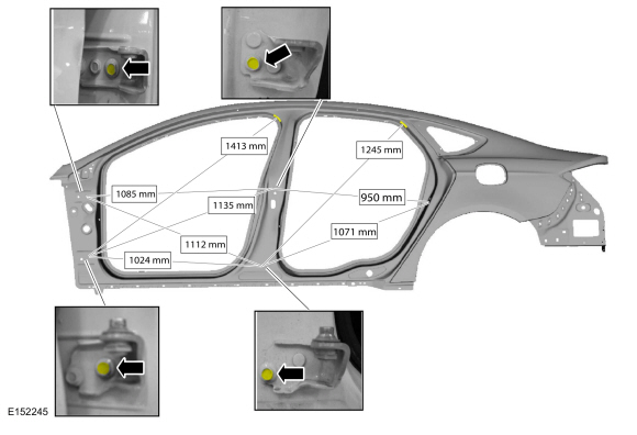
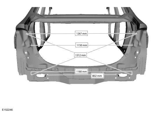
Luggage Compartment Opening Dimensions
NOTE: All measurements are on center unless otherwise indicated.
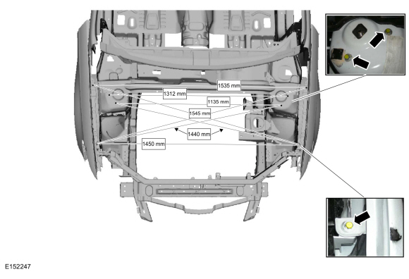
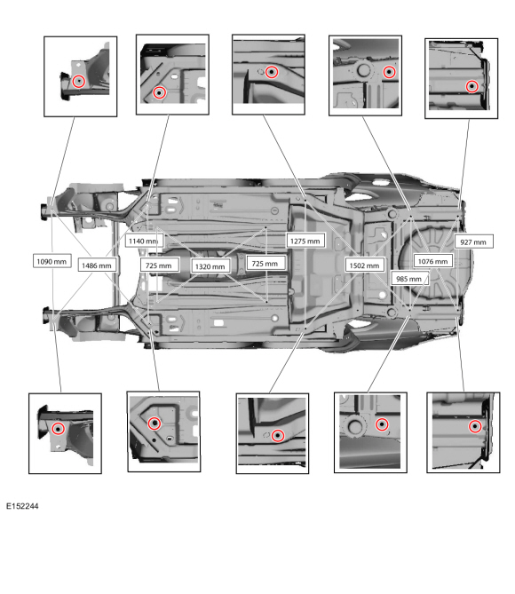
Under Body Measurements
NOTE: All measurements are on center unless otherwise indicated.
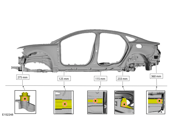
Datum Height Dimensions
NOTE: Measurements indicated below door frame openings obtained from center floor rail.

 Vehicle Specific Body Construction. Description and Operation
Before cutting or welding, For additional information, refer to: Specifications (501-25 Body Repairs - General Information, Specifications).
Bumper Beams
Bumper
beams are typically constructed of HS (high-strength) or stronger class
steel...
Other information:
Ford Fusion 2013–2020 Service Manual: Rear Halfshaft Seal. Removal and Installation
Special Tool(s) / General Equipment 205-153 (T80T-4000-W) Handle 205-990Installer, Axle SealTKIT-2012A-FLTKIT-2012A-ROW Materials Name Specification Motorcraft® SAE 80W-90 Premium Rear Axle LubricantXY-80W90-QL WSP-M2C197-A Removal Remove the rear halfshaft...
Ford Fusion 2013–2020 Service Manual: Rear Door Window Glass. Removal and Installation
Removal NOTE: LH side shown, RH side similar. NOTE: Removal steps in this procedure may contain installation details. Remove the rear door trim panel. Refer to: Rear Door Trim Panel (501-05 Interior Trim and Ornamentation, Removal and Installation)...
Categories
- Manuals Home
- 2nd Generation Ford Fusion Owners Manual
- 2nd Generation Ford Fusion Service Manual
- Pre-Collision Assist (IF EQUIPPED)
- Cylinder Head. Removal and Installation
- Body Control Module (BCM). Removal and Installation
- New on site
- Most important about car
Power Door Locks
The power door lock control is on the driver and front passenger door panels.