Ford Fusion: Side and Rear Vision / Blind Spot Information System - System Operation and Component Description. Description and Operation
System Operation
BLIS® and CTA
System Diagram
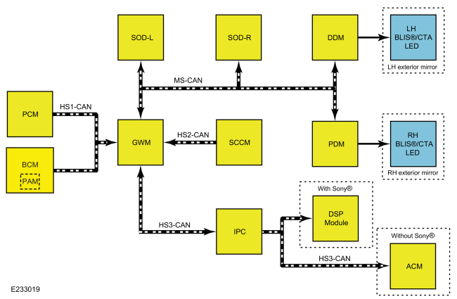
| Item | Description |
|---|---|
| 1 | SODR |
| 2 | GWM |
| 3 | IPC |
| 4 | PCM |
| 5 | SODL |
| 6 | DDM |
| 7 | PDM |
| 8 | BCM |
| 9 | PAM |
| 10 | LH exterior mirror |
| 11 | LH BLIS®/ CTA LED |
| 12 | RH exterior mirror |
| 13 | RH BLIS®/ CTA LED |
| 14 | ACM |
| 15 | Without Sony® |
| 16 | DSP module |
| 17 | With Sony® |
| 18 | SCCM |
Network Message Chart
IPC Network Input Messages
| Broadcast Message | Originating Module | Message Purpose |
| Cross traffic alert left status | SODL | Used to command the CTA audio chime and the BLIS® RTT. |
| Cross traffic alert right status | SODR | |
| Side obstacle sensor status - left | SODL | Used to communicate the operating status of the SODL and to command the BLIS®/ CTA message center displays. |
| Side obstacle sensor status - right | SODR | Used to communicate the operating status of the SODR and to command the BLIS®/ CTA message center displays. |
ACM Network Input Messages
| Broadcast Message | Originating Module | Message Purpose |
| Chime source | IPC | Used to command the CTA audio chimes on vehicles without Sony® audio system. |
DSP Network Input Messages
| Broadcast Message | Originating Module | Message Purpose |
| Chime source | IPC | Used to command the CTA audio chimes on vehicles with Sony® audio system. |
DDM Network Input Messages
| Broadcast Message | Originating Module | Message Purpose |
| BLIS®/ CTA LED command - left | SODL | Used to command the LH BLIS®/ CTA LED on and off. |
| Day/night status | BCM | Used to determine ambient lighting conditions for correct LH BLIS®/ CTA LED brightness level. |
PDM Network Input Messages
| Broadcast Message | Originating Module | Message Purpose |
| BLIS®/ CTA LED command - right | SODR | Used to command the RH BLIS®/ CTA LED on and off. |
| Day/night status | BCM | Used to determine ambient lighting conditions for correct RH BLIS®/ CTA LED brightness level. |
SODL Network Input Messages
| Broadcast Message | Originating Module | Message Purpose |
| Active park assist system status | PAM | Disables the CTA warnings during active park assist maneuvers. |
| BLIS®/ CTA enable/disable command | IPC | Used to enable/disable the BLIS® or CTA based on driver input. |
| BLIS® driver LED status | DDM | Used to confirm the operating status of the LH exterior mirror BLIS® LED. |
| Gear lever position | PCM | Used to turn the BLIS® and CTA system on and off depending the gear lever position. |
| Ignition key type | BCM | Used to disable the ability to turn OFF the BLIS® and CTA when a MyKey® restricted key is in use. |
| Turn signal status | SCCM | Used to generate the secondary alert when a turn signal is activated. |
| Vehicle speed | PCM | Used to activate the BLIS® after an ignition cycle and deactivate the CTA system when the vehicle speed exceeds preset thresholds. |
| VIN information | BCM | Contains VIN information. |
| Wiper status | SCCM | Used to determine ambient weather conditions for correct system operation. |
SODR Network Input Messages
| Broadcast Message | Originating Module | Message Purpose |
| Active park assist system status | PAM | Disables the CTA warnings during active park assist maneuvers. |
| BLIS®/ CTA enable/disable command | IPC | Used to enable/disable the BLIS® or CTA based on driver input. |
| BLIS® passenger LED status | PDM | Used to confirm the operating status of the RH exterior mirror BLIS®) LED. |
| Gear lever position | PCM | Used to turn the BLIS® and CTA system on and off depending the gear lever position. |
| Ignition key type | BCM | Used to disable the ability to turn OFF the BLIS® and CTA when a MyKey® restricted key is in use. |
| Turn signal status | SCCM | Used to generate the secondary alert when a turn signal is activated. |
| Vehicle speed | PCM | Used to activate the BLIS® after an ignition cycle and deactivate the CTA system when the vehicle speed exceeds preset thresholds. |
| VIN information | BCM | Contains VIN information. |
| Wiper status | SCCM | Used to determine ambient weather conditions for correct system operation. |
BLIS®
The BLIS® provides alerts to the driver when the vehicle is in a forward gear and the vehicle speed is greater than 10 km/h (6 mph).
The BLIS® can trigger an alert for vehicles that enter the blind zone from the rear, front, or merge into the blind zone from the side. The exterior mirror BLIS®/ CTA LED illuminates in the right and/or left exterior mirror when a target is present. For vehicles that pass through the blind zone quickly, typically less than 2 seconds, the BLIS® may not trigger an alert.
If a turn signal is active while BLIS® has detected a target in the blind zone, the BLIS®/ CTA LED flashes rapidly. When the turn signal is off, the BLIS® target warnings are a constant LED illumination.
NOTE: The BLIS® is not intended to detect parked vehicles, pedestrians, or objects such as fences, guard rails or trees.
NOTE: There should be no bumper stickers or body filler material used on the rear side bumper cover in the vicinity of the SODL or SODR.
Due to the nature of radar technology, false alerts may occur under certain circumstances. False alerts occur when the LED illuminates with no target present. False alerts up to 3% (3 out of 100 targets) are considered normal operation. False alerts are temporary and self-correcting. False alerts may be caused by sharp turns around a pole or building, jogging pedestrians or fast moving shopping carts.
Missed targets occur when a target is present and the LED does not illuminate. Missed targets up to 1% (1 out of 100 targets) are considered normal operation.
Circumstances that cause missed alerts are:
- Debris build-up, mud, snow/ice or bumper stickers on the rear bumper sides
- Certain maneuvering of the vehicles entering and exiting the blind zone
- Vehicles passing through the blind zone at high rates of speed
- When several vehicles forming a convoy pass through the blind zone
The BLIS® may not detect an adjacent target immediately when the vehicle accelerates from a standing start with another vehicle alongside.
CTA
NOTE: The CTA system is only active when reverse gear is selected.
When the transmission is in reverse, the CTA system can detect a vehicle or a bicycle that is approaching at a speed between 8 km/h and 60 km/h (5 mph and 37 mph) and time to impact is between 1 and 2.5 seconds. The distance at which an alert is generated varies depending on the speed of the approaching vehicles or bicycles. The CTA system response time and performance can degrade if vehicles are approaching at speeds greater than 60 km/h (37 mph).
An adjacent parked vehicle or object can affect the systems ability to detect approaching vehicles or bicycles (refer to figure 1). Parking at extreme angles can further affect the systems ability to detect approaching vehicles or bicycles (refer to figure 2).
Backing towards a curve road can also affect systems ability to detect approaching vehicles or bicycles (refer to figure 3).
CTA detection zones:
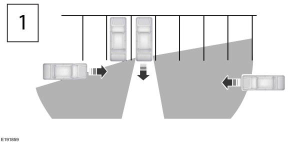
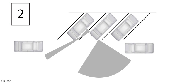
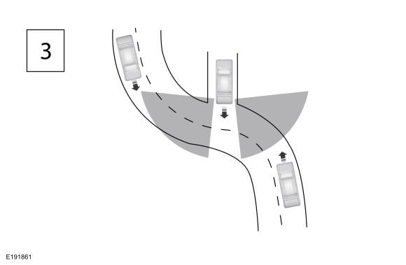
The CTA system is designed to detect objects approaching the vehicle at a speed equal to or greater than 8 km/h (5 mph). This includes vehicles and bicycles. The CTA system has some detection limitations due to the nature of the radar technology used by the SODL and SODR.
NOTE: The CTA system is not intended to detect parked vehicles, but may detect fast walking pedestrians or objects such as fences, guard rails or trees.
NOTE: There should be no bumper stickers or body filler material used on the rear side bumper cover in the vicinity of the SODL or SODR.
Circumstances that may cause non-detection are:
- Debris build-up or bumper stickers on the rear bumper sides
- The rear quarter panel of the vehicle is obstructed or partially obstructed by an adjacently parked vehicle or object
- Vehicle approaching at speeds greater than 60 km/h (37 mph)
- Driving in reverse faster than 12 km/h (8 mph)
- Damage to a sensor and/or sensor area
Due to the nature of radar technology, there may be certain instances when the CTA system alerts the operator, when no object or vehicle is present while backing up. This is known as a false alert. False alerts up to 3% of the time (3 times out of 100 reversals) are considered normal. A false alert may occur when backing out of a garage or backing into a parking space and objects or vehicles are very close to the radar sensors. False alerts are temporary and self-correcting.
Missed targets occur when a target is present and the LED does not illuminate. Missed targets up to 1% (1 out of 100 targets) is considered normal operation.
Circumstances that cause missed alerts are:
- Debris build-up or bumper stickers on the rear bumper sides
- Certain maneuvering of the vehicles entering and exiting the detection zone
- Vehicles passing through the detection zone at high rates of speed
- When several vehicles forming a convoy pass through the detection zone
Exterior Mirror Indication
When the BLIS® or CTA system is active and an object is detected by the SODL or SODR, the BLIS®/ CTA LED command message is sent from the SODL or SODR to the DDM or PDM. The DDM and PDM supply voltage and ground to illuminate their respective exterior mirror BLIS®/ CTA LED based on messages received from the SODL and SODR. There are two BLIS®/ CTA LED brightness levels, full illumination (daytime condition) and dimmed illumination (nighttime condition). The DDM and PDM control their respective exterior mirror BLIS®/ CTA LED brightness level based on a day/night message received from the BCM over the HS-CAN1 through the GWM.
Each time the vehicle is started, the SODL and SODR command the DDM and PDM to illuminate the exterior mirror BLIS®/ CTA Light Emitting Diodes (LEDs) for approximately 3 seconds, indicating the BLIS® and CTA system is operational.
If a BLIS® and/or CTA system fault is present, the exterior mirror BLIS®/ CTA Light Emitting Diodes (LEDs) remain off, the IPC BLIS® RTT illuminates and a message center warning displays BLIND SPOT SYSTEM FAULT.
BLIS® and CTA Message Center Function
NOTE: CTA system faults may not be detected until the transmission is placed in reverse.
NOTE: The BLIS® and CTA system menus in the message center are not available when a MyKey® restricted key is in use.
The BLIS® can be turned off by using the blind spot on/off function in the message center. When the BLIS® has been turned off by the driver or if a system fault is present, the BLIS® RTT in the message center remains on. When turning the system on or off, the exterior mirror Light Emitting Diodes (LEDs) flash 2 times. When the BLIS® is turned off, the driver cannot receive any alerts. The system remains off until turned back on by the driver.
The CTA system can be turned off by selecting the CTA system on/off function in the message center. The system defaults to on with each ignition cycle.
There are some system faults that set Diagnostic Trouble Codes (DTCs) in the SODL, SODR, DDM or PDM. These Diagnostic Trouble Codes (DTCs) can set a message in the IPC message center that displays BLIND SPOT SYSTEM FAULT and/or CROSS TRAFFIC SYSTEM FAULT. There are also symptom based faults that do not set a DTC.
Blocked Sensor
NOTE: Blockage sensing becomes active after the wipers are activated.
NOTE: A blocked state is not a system fault. A blocked state is a normal mode of operation under blocked conditions.
An excessive build-up of materials on the rear bumper sides, such as mud or snow, can cause the BLIS® or CTA system functionality to degrade. Heavy rain can have the same affect on the system. If a blocked state is detected, the SODL and SODR blockage sensing senses the performance degradation and enters the SODL and SODR into a blocked state. The performance degradation means alerting late on targets or additional missed targets. Upon entering a blocked state, the SODL and/or SODR send a status message over the MS-CAN to the GWM. The GWM then sends the status message to the IPC on the HS-CAN3. The message center displays BLIND SPOT NOT AVAILABLE SENSOR BLOCKED or CROSS TRAFFIC NOT AVAILABLE SENSOR BLOCKED and the LH and RH exterior mirror BLIS®/ CTA Light Emitting Diodes (LEDs) illuminate.
The message center warning can be cleared by the driver, but the amber BLIS® off RTT in the IPC remains illuminated. A blocked state will self-clear when blockage sensing senses performance has returned to normal operation. The ignition can also be cycled off to clear the blocked state. If the blockage is still present after the ignition cycle, or after some drive time the system detects again that it is blocked, the blocked sensor message is displayed again in the message center and the amber BLIS® off IPC RTT is illuminated again.
Due to the nature of radar technology, it is possible to get a blocked sensor warning without the radar sensor being blocked. This is rare and is known as a false blockage warning. A false blocked condition either self-clears or clears after an ignition cycle.
Component Description
SODL/ SODR
The SODL and SODR are radar based sensors that are located rearward of the rear wheel under the bumper cover. These sensors detect targets for the BLIS® and CTA system. The modules are capable of storing Diagnostic Trouble Codes (DTCs) for the BLIS® or CTA system when a concern exists. The SODL and SODR communicate through the MS-CAN.
The SODL and SODR require PMI when replaced.
Refer to: Module Configuration - System Operation and Component Description (418-01 Module Configuration, Description and Operation).
DDM/ PDM
The DDM and PDM supply voltage and ground to illuminate their respective exterior mirror BLIS®/ CTA LED based on messages received from the SODL and SODR. The modules are capable of storing BLIS®/ CTA LED and lost communication Diagnostic Trouble Codes (DTCs) for the BLIS® or CTA system when a concern exists. The DDM and PDM communicate through the MS-CAN.
The DDM and PDM require PMI when replaced.
Refer to: Module Configuration - System Operation and Component Description (418-01 Module Configuration, Description and Operation).
BLIS®/ CTA LED
The BLIS®/ CTA LED is integral to the LH and RH exterior mirror glass.
 Blind Spot Information System - Overview. Description and Operation
Overview
BLIS®
The BLIS®
aids the driver in assessing whether another vehicle is present within a
specific area (blind spot) to either side of the vehicle, extending
rearward approximately 6 m (20 ft) beyond the rear bumper while driving
on roads and highways...
 Blind Spot Information System. Diagnosis and Testing
DTC Chart(s)
Diagnostics in this manual assume a certain skill level and knowledge of Ford-specific diagnostic practices. REFER to: Diagnostic Methods (100-00 General Information, Description and Operation)...
Other information:
Ford Fusion 2013–2020 Owners Manual: Personal Safety System™
The Personal Safety System provides an improved overall level of frontal crash protection to front seat occupants and is designed to help further reduce the risk of airbag-related injuries. The system is able to analyze different occupant conditions and crash severity before activating the appropriate safety devices to help better protect a range of occupants in a variety of frontal crash..
Ford Fusion 2013–2020 Owners Manual: Clearing All MyKeys. Checking MyKey System Status
Clearing All MyKeys When you clear your MyKeys, you remove all restrictions and return all MyKeys to their original admin key status at once. To clear all MyKeys of all MyKey settings, use the information display. Switch the ignition on using an admin key. Access the main menu in the information display and then scroll through the menus to begin clearing your MyKey programming. Fol..
Categories
- Manuals Home
- 2nd Generation Ford Fusion Owners Manual
- 2nd Generation Ford Fusion Service Manual
- Cylinder Head. Removal and Installation
- Electrical
- Automatic Transmission - 6-Speed Automatic Transmission – 6F35
- New on site
- Most important about car
Understanding Your Tire Pressure Monitoring System
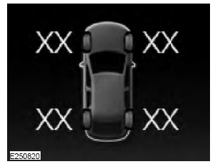
The tire pressure monitoring system measures pressure in your road tires and sends the tire pressure readings to your vehicle. You can view the tire pressure readings through the information display. The low tire pressure warning light will turn on if the tire pressure is significantly low. Once the light is illuminated, your tires are under-inflated and need to be inflated to the manufacturer’s recommended tire pressure. Even if the light turns on and a short time later turns off, your tire pressure still needs to be checked.

.jpg)