
Ford Fusion: Battery, Mounting and Cables / Battery Current Sensor. Removal and Installation
Ford Fusion 2013–2020 Service Manual / Electrical / Battery and Charging System / Battery, Mounting and Cables / Battery Current Sensor. Removal and Installation
Removal
-
Follow the health and safety precautions. WARNING:
Before beginning any service procedure in this
section, refer to Safety Warnings in section 100-00 General Information.
Failure to follow this instruction may result in serious personal
injury.
WARNING:
Before beginning any service procedure in this
section, refer to Safety Warnings in section 100-00 General Information.
Failure to follow this instruction may result in serious personal
injury.
Refer to: Health and Safety Precautions (100-00 General Information, Description and Operation).
-
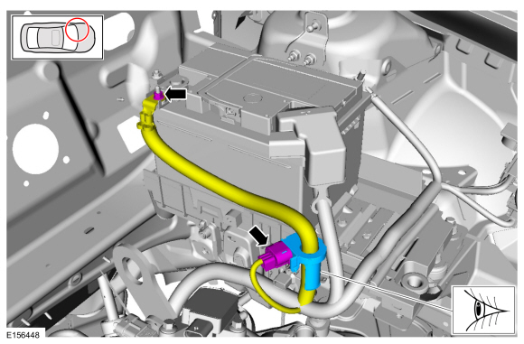
NOTE: 2.5L shown, other engines similar.
NOTE: Note the orientation and position of the battery current sensor tape tab.
Index-mark the battery cable at the battery current sensor. Remove and discard the tape securing the battery current sensor to the battery cable and remove the battery current sensor.
 |
Installation
-
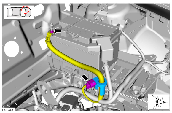
NOTE: 2.5L shown, other engines similar.
NOTE: The battery current sensor must be installed in the proper position and orientation to function correctly.
With the battery current sensor tape tab pointing away from the battery, position the battery current sensor to the index-mark on the battery cable and secure with electrical tape.
Torque: 80 lb.in (9 Nm)
 |
 Battery Cables - 1.5L EcoBoost (118kW/160PS) – I4. Removal and Installation
Removal
NOTE:
This procedure provides information about routing, retaining
points and connectors of the cable. It does not include the steps for
removing components to gain access to the cable...
 Battery Monitoring Sensor. Removal and Installation
Removal
NOTICE:
Do not remove or install the M8 nut (20 Nm) on the cable
eyelet bolt while the battery monitoring sensor is attached to the
battery post as this causes damage to the sensor, connector, and
possibly the battery post and case...
Other information:
Ford Fusion 2013–2020 Owners Manual: At a Glance
INSTRUMENT PANEL Air vents. Direction indicators. See Direction Indicators. Information display controls. See Information Display Control. Instrument cluster. See Instrument Cluster. Information display controls. See Information Display Control...
Ford Fusion 2013–2020 Service Manual: Cylinder Block Core Plug Replacement. General Procedures
Special Tool(s) / General Equipment 100-001 (T50T-100-A) Slide Hammer Materials Name Specification Motorcraft® Threadlock 262TA-26 WSK-M2G351-A6 Repair All core plugs NOTE: Cylinder block core plug shown, cylinder head core plug similar...
Categories
- Manuals Home
- 2nd Generation Ford Fusion Owners Manual
- 2nd Generation Ford Fusion Service Manual
- Body Control Module (BCM). Removal and Installation
- Electrical
- Powertrain
- New on site
- Most important about car
Power Door Locks
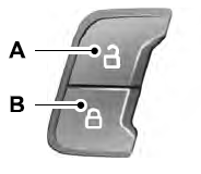
The power door lock control is on the driver and front passenger door panels.

Copyright © 2026 www.fofusion2.com