Ford Fusion: Wheels and Tires / Wheel and Tire. Disassembly and Assembly
Special Tool(s) / General Equipment
| Wooden Block |
DISASSEMBLY
NOTICE: Ford Recommends The Following For Vehicles With Carbon Fiber And Alloy Wheels:
-
Tire Changer:
- Ford requires center clamp style tire changers such as Hunter® Auto 34, Revolution, TC3900 or equivalent. Anything else, especially table top style machines, are highly likely to damage the wheel which is not warrantable. Do not use table top design machines that grab onto the inside of the wheel and that ride on the front wheel flange to remove the tire. Wheel damage will occur.
-
Tire Balancer:
- Ford requires the use of wheel balancers that do not contact the wheel face such as, Hunter® Road Force Touch GSP9700. Do not use machines that contact the wheel face. Wheel damage will occur.
NOTICE: Failure to follow the instructions below may result in damage to the TPMS.
NOTICE: The TPMS sensor is mounted to the valve stem. Removal of the valve stem requires dismounting the tire from the wheel and removal of the TPMS sensor.
NOTE: Use only the Digital Tire Pressure Gauge any time tire pressures are measured to be sure that accurate values are obtained.
-
Remove the wheel and tire.
Refer to: Wheel and Tire (204-04A Wheels and Tires, Removal and Installation).
-
NOTICE: The valve stem is connected to the TPMS sensor. Do not pull the valve stem from the wheel, or damage to the sensor will occur.
NOTE: If a new TPMS sensor is being installed, remove and discard the valve stem-to-sensor screw and the sensor.
Remove the valve stem core and fully deflate all air from the tire.
-
NOTICE: Do not allow the tire beads to move beyond the wheel mid-plane (middle of the wheel) when separating the beads from the wheels, damage to the TPMS sensor may occur.
NOTICE: Tire and valve stem position is critical to prevent damage to theTPMS sensor when using a paddle-type bead separator.
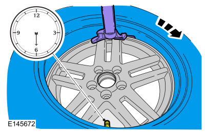
NOTE: Some machines may have a nylon roller bead separator at the 12 o'clock position instead of the paddle-type bead separator at the 3 o'clock position.
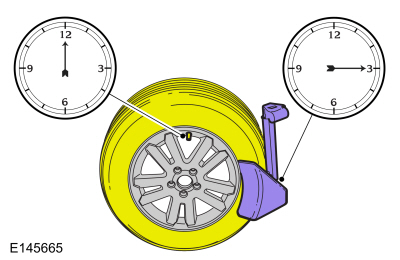
- For a paddle-type tire machine, position the valve stem at the 12 o'clock or 6 o'clock position and the paddle at the 3 o'clock position.
- For a roller-type tire machine, align the valve stem with the roller at any position.
NOTE: Paddle type shown, roller type similar.
 |
-
NOTE: Index-mark the valve stem and wheel weight positions on the tire.
Place the wheel and tire assembly on the turntable of the tire machine with the valve stem at the 11:30 position and the machine arm at the 12 o'clock position and dismount the outer bead from the wheel.
 |
-
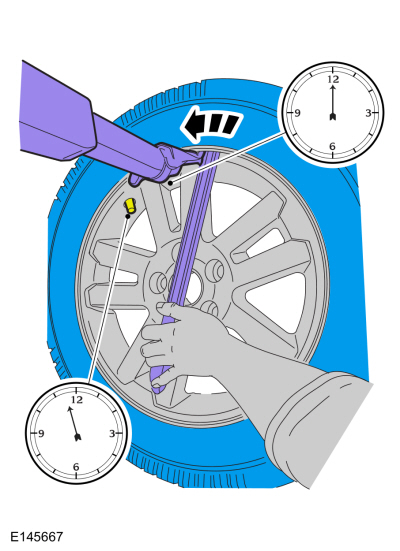
Reset the wheel and tire assembly on the turntable of
the tire machine with the valve stem at the 11:30 position and the
machine arm at the 12 o'clock position and dismount the inner bead from
the wheel.
-
NOTE: A new valve stem must be installed whenever a new tire or wheel is installed.
-
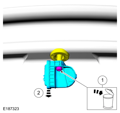
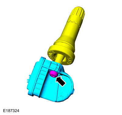
Remove and discard the TPMS sensor-to-valve stem screw.
-
Separate the TPMS sensor from the valve stem.
-
Remove and discard the TPMS sensor-to-valve stem screw.
 |
-
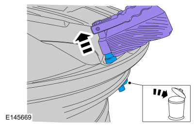
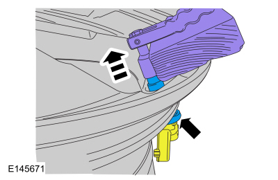
NOTICE: Use care not to damage the wheel surface when removing the valve stem.
Using a suitable valve stem remover/installer, remove and discard the valve stem.
Use the General Equipment: Wooden Block
 |
NOTE: When installing a new wheel, always install a new valve stem and sensor screw. Reuse theTPMS sensor from the previous wheel if possible. The TPMS will not have to be trained if the sensor is reused.
NOTE: If the TPMS sensor is being reused, inspect the TPMS sensor for damage and install a new sensor as necessary.
-
NOTICE: To prevent TPMS sensor and valve stem damage, the valve stem must be installed onto the TPMS sensor and then installed into the wheel as an assembly.
Position the new valve stem onto the TPMS sensor and install the new screw.
Torque: 13 lb.in (1.5 Nm)
 |
ASSEMBLY
NOTICE: Damage to the TPMS sensor may result if the tire mounting is not carried out as instructed.
-
NOTICE: It is important to pull the valve stem and TPMS sensor assembly through the wheel rim hole in a direction parallel to the valve stem hole axis. If the assembly is pulled through at an angle, damage to the valve stem and sensor assembly may occur.
NOTICE: Use care not to damage the wheel surface when installing the valve stem and TPMS sensor assembly.
NOTE: Lubricate the valve stem with soapy water and install the valve stem and TPMS sensor assembly into the wheel using a block of wood and a suitable valve stem installer.
Using a suitable valve stem installer, install the new valve stem and TPMS sensor assembly.
Use the General Equipment: Wooden Block
 |
-
NOTE: Lubricate the tire beads using a suitable fast-drying, corrosion-inhibiting tire bead lubricant.
NOTE: Do not mount the tire at this time.
Position the wheel on the turntable of the tire machine, then lubricate and position the bottom bead of the tire on the wheel.
-
Position the wheel to align the valve stem with the
machine arm, at the 6 o'clock position, and mount the bottom bead of the
tire.
 |
-
Reposition the wheel to align the valve stem with the
machine arm at the 6 o'clock position, and mount the top bead of the
tire.
-
NOTE: Use only the Digital Tire Pressure Gauge any time tire pressures are measured to be sure that accurate values are obtained.
Inflate the tire to the pressure specified on the VC label located on the driver door or door pillar.
NOTE: Proceed to the next step if the tire beads do not seat at the specified inflation pressure.
-
 WARNING:
If there is a need to exceed the maximum pressure
indicated on the sidewall of the tire in order to seat the beads, follow
all steps listed below. Failure to follow these steps may result in
serious personal injury.
WARNING:
If there is a need to exceed the maximum pressure
indicated on the sidewall of the tire in order to seat the beads, follow
all steps listed below. Failure to follow these steps may result in
serious personal injury.
NOTICE: The following steps should only be carried out if the tire beads cannot be seated by inflating the tire up to the maximum inflation pressure listed on the tire sidewall.
-
Relubricate the tire bead and wheel bead seat area.
-
Install a remote valve and pressure gauge.
-
Wear eye and ear protection and stand at a minimum of 3.65 m (12 ft) away from the wheel and tire assembly.
-
Inflate the tire using the remote valve and tire
gauge until the beads have seated or until the pressure gauge is 138 kPa
(20 psi) more than maximum inflation pressure on tire sidewall. If
beads have not seated, deflate the tire and proceed to the next step.
-
Place the wheel and tire assembly in an OSHA-approved tire safety cage.
-
Inflate the tire using the remote valve and pressure
gauge until the beads have seated or until the pressure gauge is 276
kPa (40 psi) more than maximum inflation pressure on the tire sidewall. Do
not exceed 276 kPa (40 psi) above the maximum pressure on tire
sidewall. Install a new tire if the beads do not seat at this pressure.
-
Relubricate the tire bead and wheel bead seat area.
-
Install the wheel and tire.
Refer to: Wheel and Tire (204-04A Wheels and Tires, Removal and Installation).
 Wheel and Tire. Removal and Installation
Materials
Name
Specification
Motorcraft® High Temperature Nickel Anti-Seize LubricantXL-2
-
Removal
With the vehicle in NEUTRAL, position it on a hoist...

Other information:
Ford Fusion 2013–2020 Owners Manual: Principle of Operation
MyKey allows you to program keys with restricted driving modes to promote good driving habits. You can program the restrictions to all keys except one. Any keys that you did not program are administrator keys or admin keys. You can use admin keys to: Create a MyKey with certain vehicle restrictions. Program certain MyKey settings. Clear all MyKey restrictions. After you program a MyKey..
Ford Fusion 2013–2020 Service Manual: Connecting Rod Bearing Journal Clearance. General Procedures
Check NOTE: Refer to the appropriate Section 303-01 for the specification. NOTE: The crankshaft connecting rod journals must be within specifications to check the connecting rod bearing journal clearance. Remove the connecting rod bearing cap and connecting rod bearing. Position a piece of Plastigage across the bearing surface. NOTE: D..
Categories
- Manuals Home
- 2nd Generation Ford Fusion Owners Manual
- 2nd Generation Ford Fusion Service Manual
- Garage Door Opener
- Body Control Module (BCM). Removal and Installation
- Traction Control
- New on site
- Most important about car
Direction Indicators. Interior Lamps
Direction Indicators

Push the lever up or down to use the direction indicators.