Ford Fusion: Engine - 1.5L EcoBoost (118kW/160PS) – I4 / Valve Clearance Adjustment. General Procedures
Special Tool(s) / General Equipment
| Feeler Gauge | |
| Hot Air Gun | |
| Hose Clamp Remover/Installer |
Materials
| Name | Specification |
|---|---|
| Flange Sealant CU7Z-19B508-A |
WSS-M2G348-A11 |
| Engine Oil - SAE 5W-20 - Synthetic Blend Motor Oil XO-5W20-Q1SP |
WSS-M2C945-B1 |
Check
-
With the vehicle in NEUTRAL, position it on a hoist.
Refer to: Jacking and Lifting - Overview (100-02 Jacking and Lifting, Description and Operation).
-
Remove the following items:
-
Remove the valve cover.
Refer to: Valve Cover (303-01A Engine - 1.5L EcoBoost (118kW/160PS) – I4, Removal and Installation).
-
Remove the high-pressure fuel pump drive unit.
Refer to: High-Pressure Fuel Pump Drive Unit (303-04A Fuel Charging and Controls - 1.5L EcoBoost (118kW/160PS) – I4, Removal and Installation).
-
Remove the upper air cleaner outlet pipe.
Refer to: Air Cleaner Outlet Pipe (303-12A Intake Air Distribution and Filtering - 1.5L EcoBoost (118kW/160PS) – I4, Removal and Installation).
-
Remove the air cleaner.
Refer to: Air Cleaner (303-12A Intake Air Distribution and Filtering - 1.5L EcoBoost (118kW/160PS) – I4, Removal and Installation).
-
Remove the valve cover.
-
-
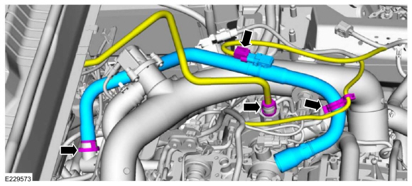
Disconnect the wiring harness electrical connector and retainer.
-
Disconnect the coupling and remove the PCV hose.
-
Disconnect and position the brake vacuum hose aside.
-
Disconnect the wiring harness electrical connector and retainer.
 |
-
-
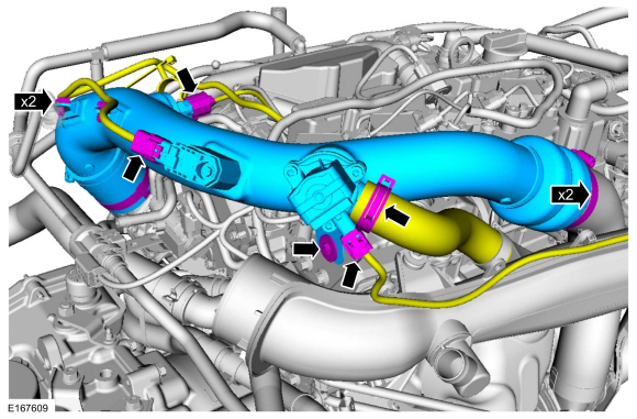
Detach the wiring harness retainers and disconnect the electrical connectors.
-
Disconnect the TC bypass hose.
-
Loosen the clamps, remove the bolt and the TC outlet pipe.
Use the General Equipment: Hose Clamp Remover/Installer
-
Detach the wiring harness retainers and disconnect the electrical connectors.
 |
-
Disconnect the wiring harness electrical connector and retainer.
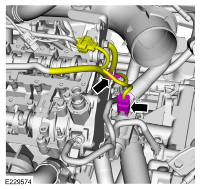 |
-
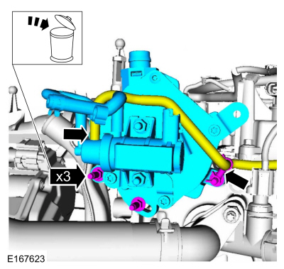
Remove the nuts, bracket and position the EVAP canister purge valve aside.
 |
-
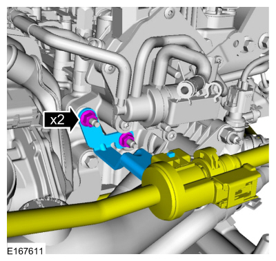
-
Detach the retainer and disconnect the vacuum hose.
-
Remove the stud bolts and the vacuum pump. Discard the stud bolts.
-
Detach the retainer and disconnect the vacuum hose.
 |
-
Remove and discard the vacuum pump gasket.
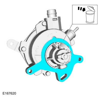 |
-
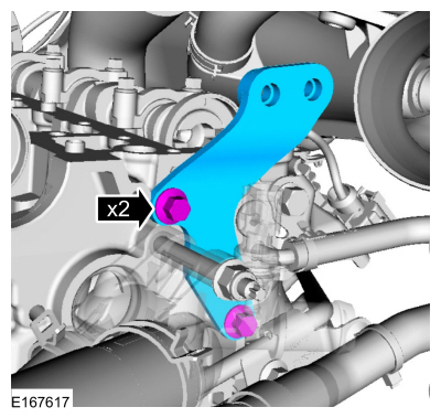
Remove the bolts and the support bracket.
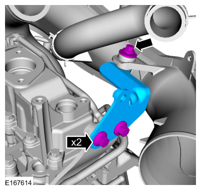 |
-
-
Remove the engine cover mounting stud.
-
Remove the bolts and the stud.
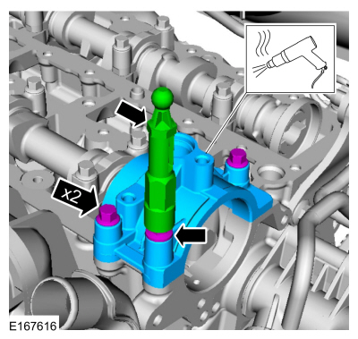
-
Heat and break the adhesive bond and remove the brake vacuum pump cap.
Use the General Equipment: Hot Air Gun
-
Remove the engine cover mounting stud.
 |
-
Remove the bolts and the engine lifting bracket.
 |
-
NOTICE: Only use hand tools when removing or installing the spark plugs, or damage can occur to the cylinder head or spark plug.
NOTE: Use compressed air to remove any foreign material in the spark plug well before removing the spark plugs.
Remove the spark plugs.
 |
-
Remove the retainers and the engine undershield.
 |
-
NOTE: Measure the valve clearance at base circle, with the lobe pointed away from the tappet, before removing the camshafts. Failure to measure all clearances prior to removing the camshafts will necessitate repeated removal and installation and wasted labor time.
Measure each valve's clearance and record its location.
Use the General Equipment: Feeler Gauge
 |
-
NOTE: The nominal clearance is:
- intake: 0.0112 in (0.285 mm)
- exhaust: 0.0167 in (0.425 mm)
NOTE: The acceptable clearance is:
- intake: 0.009–0.013 in (0.24–0.33 mm)
- exhaust: 0.015–0.019 in (0.38–0.47 mm)
Adjustment
-
Remove the camshafts.
Refer to: Camshafts (303-01A Engine - 1.5L EcoBoost (118kW/160PS) – I4, Removal and Installation).
-
NOTE: The number on the valve tappet only reflects the digits that follow the decimal. For example, a tappet with the number '3,125' has the thickness of 3.125 mm.
NOTE: Select the closest tappet size to the ideal tappet thickness available and mark the installation location.
Select tappets using this formula: tappet thickness = measured clearance + the existing tappet thickness - nominal clearance.
-
Install the correct valve tappet.
-
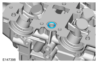
NOTE: Install a new O-ring seal.
Install the new O-ring seal.
 |
-
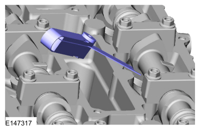
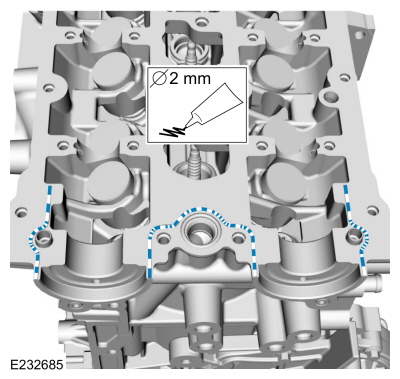
Apply a 2.0 mm bead of flange sealant.
Material: Flange Sealant / CU7Z-19B508-A (WSS-M2G348-A11)
 |
-
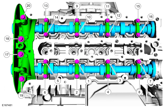
NOTE: Make sure that the components are installed to the position noted before removal.
NOTE: Make sure that new bolts are installed.
NOTE: Apply clean engine oil to the bearing surfaces of the camshafts, camshaft bearing caps and the VCT bridge.
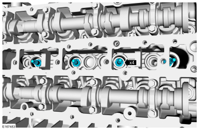
Install the camshafts approximately at valve overlap position cylinder No. 4. Install the camshaft caps and tighten the bolts evenly, half turn at a time, until the crankshaft bearing caps and the VCT bridge are seated against the cylinder head.
Material: Engine Oil - SAE 5W-20 - Synthetic Blend Motor Oil / XO-5W20-Q1SP (WSS-M2C945-B1)
Torque:
Stage 1: 1 - 16: 62 lb.in (7 Nm)
Stage 2: 17 - 20: 89 lb.in (10 Nm)
Stage 3: 1 - 16: 45°
Stage 4: 17 and 18: 70°
Stage 5: 19 and 20: 53°
 |
-
-
Turn the crankshaft back by 45° (counterclockwise).
-
Turn the camshafts to measure the valve clearance,
-
Repeat the procedure as necessary until all the valve clearances are within specifications.
-
Turn the crankshaft clockwise until it stops against the special tool.
-
Turn the crankshaft back by 45° (counterclockwise).
-
NOTICE: Only use hand tools when removing or installing the spark plugs, or damage can occur to the cylinder head or spark plug.
NOTE:
Install the spark plugs.
Torque: 115 lb.in (13 Nm)
 |
-
Install the camshafts seals.
Refer to: Camshaft Seal (303-01A Engine - 1.5L EcoBoost (118kW/160PS) – I4, Removal and Installation).
-
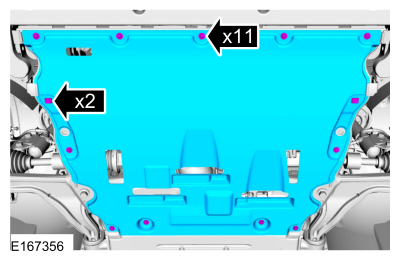
Install the engine undershield and the retainers.
 |
 Engine. Diagnosis and Testing
REFER to: Engine (303-00 Engine System - General Information, Diagnosis and Testing). For basic mechanical concerns or to the Powertrain Control/Emissions Diagnosis (PC/ED) manual for driveability concerns...
 Camshafts. Removal and Installation
Special Tool(s) /
General Equipment
303-1532Installer, Camshaft SealTKIT-2010B-FLMTKIT-2010B-ROW
303-393-02Adapter for 303-393TKIT-2012A-FLTKIT-2012A-ROW
303-393ALocking Tool, FlywheelTKIT-2012A-FLTKIT-2012A-ROW
303-409
(T92C-6700-CH)
Remover, Crankshaft SealTKIT-1992-FH/FMH/FLMHTKIT-1993-LMH/MH
303-748Locking Tool, CrankshaftTKIT-2010B-FLMTKIT-2010B-ROW
F..
Other information:
Ford Fusion 2013–2020 Service Manual: Rear Door Speaker. Removal and Installation
Removal NOTE: Removal steps in this procedure may contain installation details. Remove the rear door trim panel. Refer to: Rear Door Trim Panel (501-05 Interior Trim and Ornamentation, Removal and Installation). Remove the bolts and the door midwoofer speaker. Disconnect the electrical connector. Torque: 22 lb.in (2.5 Nm) Install..
Ford Fusion 2013–2020 Owners Manual: Interior Mirror. Sun Visors
Interior Mirror WARNING: Do not adjust the mirrors when your vehicle is moving. This could result in the loss of control of your vehicle, serious personal injury or death. Note: Do not clean the mirror housing or glass with harsh abrasives, fuel or other petroleum-based cleaning products. You can adjust the interior mirror to your preference. Some mirrors also have a second pivot point. Thi..
Categories
- Manuals Home
- 2nd Generation Ford Fusion Owners Manual
- 2nd Generation Ford Fusion Service Manual
- Powertrain
- Engine - 1.5L EcoBoost (118kW/160PS) – I4
- Automatic Transmission - 6-Speed Automatic Transmission – 6F35
- New on site
- Most important about car
Cross Traffic Alert System Sensors
The sensors are behind the rear bumper on both sides of your vehicle.