Ford Fusion: Automatic Transmission - 6-Speed Automatic Transmission – 6F35 / Transmission Description - System Operation and Component Description. Description and Operation
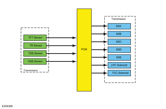
System Diagram
.jpg)
| Item | Description |
|---|---|
| 1 | SSB |
| 2 | SSC |
| 3 | SSD |
| 4 | SSE |
| 5 | LPC Solenoid |
| 6 | TCC Solenoid |
| 7 | OSS Sensor |
| 8 | TSS Sensor |
| 9 | Transmission |
| 10 | Transmission |
| 11 | TR Sensor |
| 12 | TFT Sensor |
| 13 | SSA |
| 14 | PCM |
Network Message Chart
| Broadcast Message | Originating Module | Message Purpose |
|---|---|---|
| Engine Speed | PCM | Directly affects shift scheduling, TCC control, line pressure and transmission diagnostics. Indirectly affects shift pressure control. |
| Engine torque estimate | PCM | Directly affects shift pressure control, TCC control and transmission diagnostics. Indirectly affects shift scheduling and TCC scheduling. |
| APP | PCM | Directly affects shift scheduling, TCC scheduling and transmission diagnostics. Indirectly affects TCC control and shift control. |
| Commanded engine torque | PCM | Directly affects shift scheduling, TCC scheduling and transmission diagnostics. Indirectly affects shift control. |
| BPP | PCM | Directly affects shift scheduling and TCC scheduling |
System Operation
The PCM and its input/output network controls the following operations:
Shift timing
Line pressure (shift feel)
The transmission control strategy is separate from the engine control strategy in the PCM, although some of the input signals are shared. When determining the best operating strategy for transmission operation, the PCM uses input information from engine and driver related sensors and switches.
In addition, the PCM receives input signals from transmission related sensors and switches. The PCM uses these signals when determining transmission operating strategy.
Using all of these input signals, the PCM can determine when the time and conditions are right for a shift or when to apply or release the TCC. It also determines the best line pressure to optimize shift engagement feel. To accomplish this, the PCM uses output solenoids to control transmission operation.
Component Description
Sensors and Switches
The PCM controls the electronic functions of this transmission. The PCM receives input signals from engine and transmission sensors and uses these inputs to control line pressure, shift time, TCC and shift solenoids.
| Item | Description |
| TFT Sensor | This sensor is located in the transmission internal wiring harness frame. It is a temperature-sensitive device called a thermistor. The resistance value of the TFT sensor will vary with temperature change. The PCM monitors the voltage across the TFT sensor to determine the temperature of the transmission fluid. The PCM uses this initial signal to determine whether a cold start shift schedule is necessary. The cold start shift schedule allows delayed shifts when the transmission fluid is cold to help warm the transmission fluid. The PCM also inhibits TCC operation at low transmission fluid temperatures and adjusts line pressure for temperature. |
| TR Sensor | The TR sensor assembly is an internally mounted sensor located on the manual control lever shaft. The TR sensor contains electronic circuitry that provides the PCM a fixed frequency duty cycle for each of the various positions of the manual lever (PARK, REVERSE, NEUTRAL, (D), and L) to the PCM. The PCM uses the TR sensor signal for engine start, reverse lamps and for line pressure control, shift scheduling and TCC operation. |
| TSS Sensor | The TSS sensor is a Hall-effect type sensor that provides a TSS signal to the PCM. The TSS signal changes in frequency as the rotating speed of the trigger wheel, part of the direct clutch cylinder, varies. The TSS information is compared to engine rpm to determine TSS performance. The TSS is also compared to the OSS to determine shift quality and clutch performance. |
| OSS Sensor | The OSSsensor is a Hall-effect type sensor that provides an OSS signal to the PCM. The OSS signal changes in frequency as the rotating speed of the trigger wheel, part of the park gear, varies. The OSS is used for shift scheduling. The OSS is also compared to the TSS to determine shift quality and clutch performance. |
System Diagram
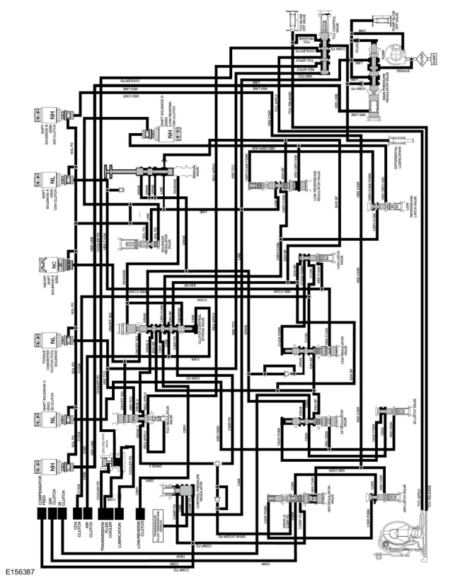
Hydraulic Circuit Identification Chart
| Circuit Name | Description |
| BYPASS | Pressure from the main pressure regulator valve to the pump assembly suction circuit for line pressure control. |
| C1234 | Regulated line pressure from the 1234 regulator valve supplied to the forward (1, 2, 3, 4) clutch to apply the clutch. |
| C1234 FDBK | C1234 pressure from the 1234 latch valve supplied to the 1234 regulator valve to oppose movement of the valve from VBS C1234 pressure during forward (1, 2, 3, 4) clutch application. |
| C35R | Regulated line pressure from the 35R regulator valve supplied to the direct (3, 5, R) clutch to apply the clutch. |
| C35R FD | Line pressure from the REVERSE circuit supplied to the DRIVE 2/C35R FD shuttle valve by the clutch control bypass valve to supply the 35R regulator valve with line pressure in reverse. |
| C35R FDBK | C35R pressure from the 35R latch valve supplied to the 35R regulator valve to oppose movement of the valve from VBS C35R pressure during direct (3, 5, R) clutch application. |
| C456 | Regulated line pressure from the low reverse/456 regulator valve directed to the overdrive (4, 5, 6) clutch by the clutch control bypass valve. C456 also provides latch pressure for the clutch control bypass valve. |
| CB26 | Regulated line pressure from the 26 regulator valve to the intermediate (2, 6) clutch to apply the clutch in 2nd and 6th gears. |
| CB26 FDBK | CB26 pressure from the 26 latch valve supplied to the 26 regulator valve to oppose movement of the valve from VBS C26 pressure during intermediate (2, 6) clutch application. |
| CBR1 | Regulated line pressure from the low reverse/456 regulator valve directed to the low/reverse clutch by the clutch control bypass valve. |
| CBR1/C456 | Regulated line pressure from the low reverse/456 regulator valve to the clutch control bypass valve. |
| CBR1/C456 FDBK | CBR1/C456 pressure from the low reverse/456 latch valve supplied to the low reverse/456 regulator valve to oppose movement of the valve from VBS CBR1/456 pressure during low/reverse or overdrive (4, 5, 6) clutch application. |
| COMP FD | Pressure supplied to the opposite side of the overdrive (4, 5, 6) and direct (3, 5, R) clutch apply pistons to oppose centrifugal application of the clutches. |
| CONV FD | Line pressure from the main pressure regulator valve supplied to the TCC control valve for TCC release. |
| COOLER FD | Return pressure from the torque converter during TCC release that is directed to the transmission fluid cooler by the TCC control valve. |
| DRIVE | Line pressure directed to the clutch control bypass valve, 1234 regulator valve and the 26 regulator valve by the manual valve in the DRIVE position. |
| DRIVE 2 | DRIVE pressure directed to the TCC regulator valve and the DRIVE 2/C35R FD shuttle valve by the clutch control bypass valve to supply the 35R regulator valve with line pressure in 3rd and 5th gears. |
| DRIVE 2/C35R FD | DRIVE 2 or C35R FD pressure supplied to the 35R regulator valve from the DRIVE 2/C35R FD shuttle valve during direct (3, 5, R) clutch application. |
| EXH | Fluid exhausted from the valves that drains to the sump area. |
| EXH BF | Unpressurized fluid from the manual valve that fills the unused hydraulic circuits. |
| LINE | Pressure from the pump to the control pressure regulator, solenoid regulator valve, manual valve and low reverse/456 regulator valve. Line pressure is regulated by the main pressure regulator valve. |
| LUBE | Transmission lubrication circuit (through the input shaft) |
| ON/OFF SIG | Full solenoid output pressure from SSE to the clutch control bypass valve and the TCC regulator valve. ON/OFF SIG pressure positions the clutch control bypass valve to apply either the low/reverse clutch or the overdrive (4, 5, 6) clutch. |
| REG APPLY | Regulated DRIVE 2 pressure supplied to the TCC control valve by the control pressure regulator for TCC application. |
| REVERSE | Line pressure directed to the clutch control bypass valve by the manual valve in the REVERSE position. |
| SOL FD | Regulated line pressure supplied to the shift, TCC and LPC solenoids. |
| TCC APPLY | Pressure supplied to the torque converter by the TCC control valve to apply the clutch. TCC APPLY is also the return circuit for the TCC RELEASE circuit. |
| TCC RELEASE | Pressure supplied to the torque converter by the TCC control valve to release the clutch. TCC RELEASE is also the return circuit for the TCC APPLY circuit. |
| VBS C1234 | Variable SOL FD pressure supplied to the 1234 regulator valve and 1234 latch valve by SSA to position the valves to apply the forward (1, 2, 3, 4) clutch. |
| VBS C35R | Variable SOL FD pressure supplied to the 35R regulator valve and 35R latch valve by SSB to position the valves to apply the direct (3, 5, R) clutch. |
| VBS CB26 | Variable SOL FD pressure supplied to the 26 regulator valve and 26 latch valve by SSC to position the valves to apply the intermediate (2, 6) clutch. |
| VBS CBR1/456 | Variable SOL FD pressure supplied to the low reverse/456 regulator valve and low reverse/456 latch valve by SSD to position the valves to apply the low/reverse clutch or overdrive (4, 5, 6) clutch. |
| VBS LINE | Variable SOL FD pressure supplied to the main pressure regulator valve by the LPC solenoid to control line pressure. |
| VBS TCC | Variable SOL FD pressure supplied to the TCC regulator valve and TCC control valve to position the valves by the TCC solenoid to apply the TCC. |
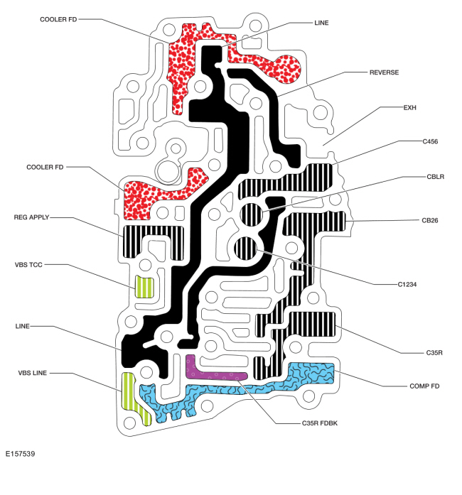
Valve Body Maps for Solenoid and Line Pressure
Solenoid Body Hydraulic Passages
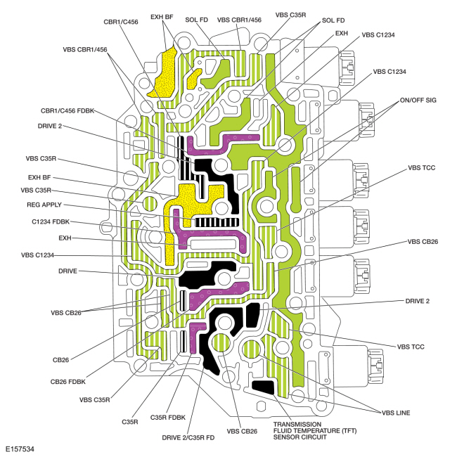
Solenoid Body-to-Valve Body Separator Plate Hydraulic Passages
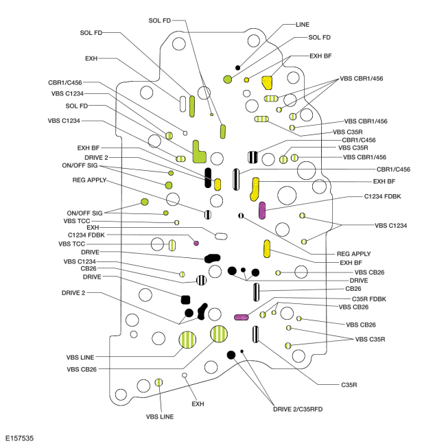
Valve Body Hydraulic Passages (Front View)
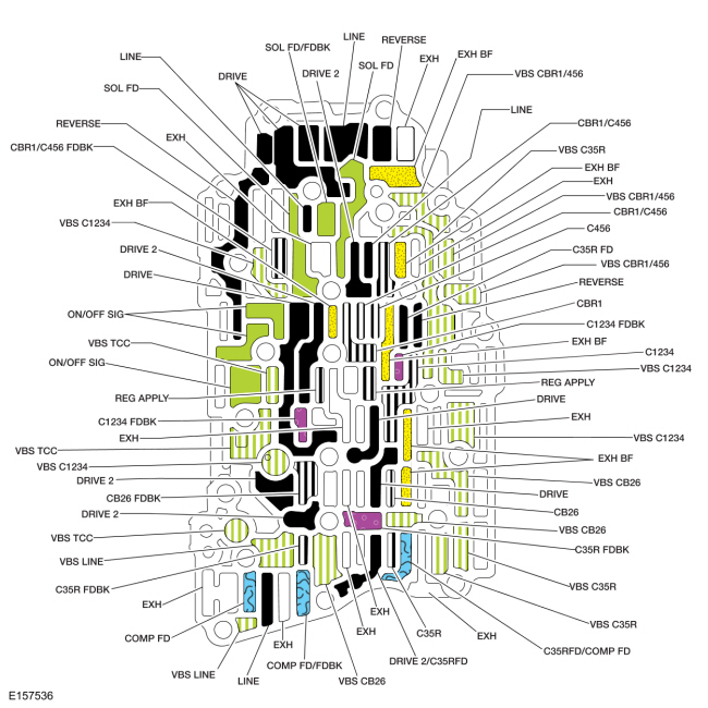
Valve Body Hydraulic Passages (Rear View)
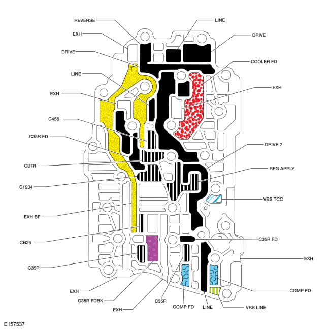
Valve Body-to-Transmission Case Separator Plate Hydraulic Passages
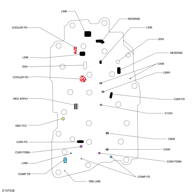
Transmission Case Hydraulic Passages
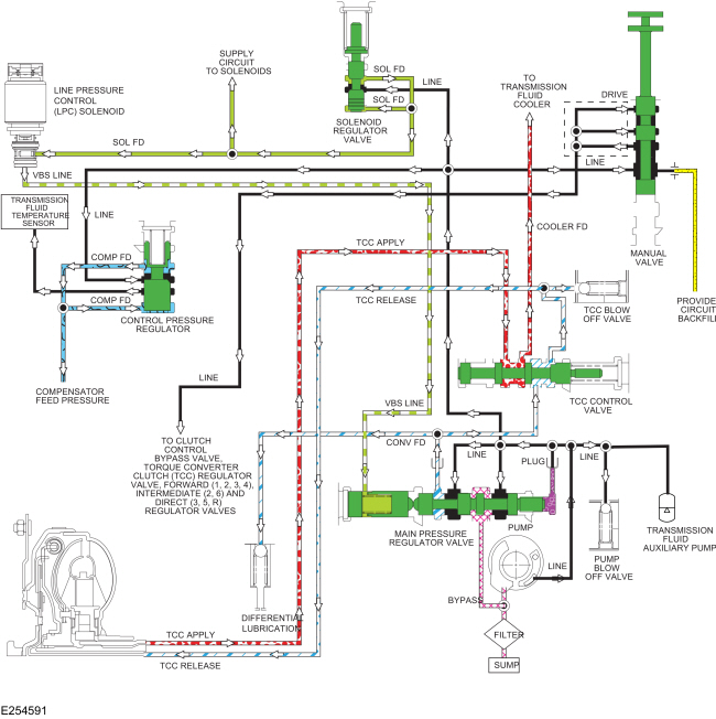
.jpg)
| Item | Description |
|---|---|
| 1 | TRANSMISSION FLUID TEMPERATURE SENSOR |
| 2 | PLUG |
| 3 | PUMP |
| 4 | FILTER |
| 5 | SUMP |
| 6 | PUMP BLOW OFF VALVE |
| 7 | TRANSMISSION FLUID AUXILIARY PUMP |
| 8 | MAIN PRESSURE REGULATOR VALVE |
| 9 | TCC CONTROL VALVE |
| 10 | DIFFERENTIAL LUBRICATION |
| 11 | TCC BLOW OFF VALVE |
| 12 | MANUAL VALVE |
| 13 | SOLENOID REGULATOR VALVE |
| 14 | CONTROL PRESSURE REGULATOR |
| 15 | LINE PRESSURE CONTROL (LPC) SOLENOID |
| 16 | TO CLUTCH CONTROL BYPASS VALVE, TORQUE CONVERTER CLUTCH (TCC) REGULATOR VALVE, FORWARD (1, 2, 3, 4), INTERMEDIATE (2, 6) AND DIRECT (3, 5, R) REGULATOR VALVES |
| 17 | COMPENSATOR FEED PRESSURE |
| 18 | PROVIDES CIRCUIT BACKFILL |
| 19 | SUPPLY CIRCUIT TO SOLENOIDS |
| 20 | TO TRANSMISSION FLUID COOLER |
| 21 | LINE |
| 22 | LINE |
| 23 | LINE |
| 24 | LINE |
| 25 | LINE |
| 26 | LINE |
| 27 | LINE |
| 28 | DRIVE |
| 29 | BYPASS |
| 30 | VBS LINE |
| 31 | VBS LINE |
| 32 | COOLER FD |
| 33 | TCC APPLY |
| 34 | TCC APPLY |
| 35 | TCC RELEASE |
| 36 | TCC RELEASE |
| 37 | COMP FD |
| 38 | COMP FD |
| 39 | SOL FD |
| 40 | SOL FD |
| 41 | SOL FD |
| 42 | CONV FD |
Line pressure is controlled by the LPC solenoid, which is controlled by the PCM. This effects shift feel and apply component operation.
When the engine is running, the pump supplies pressure to the main pressure regulator valve, which is controlled by the LPC solenoid. The main pressure regulator valve controls the line pressure to the LINE circuit which supplies the manual valve solenoid regulator valve and the control pressure regulator valve.
When the manual valve is in the reverse position, it supplies the clutch control bypass valve with line pressure to position it to supply line pressure to the direct (3, 5, R) regulator valve and regulated line pressure to the low/reverse clutch to apply the clutch.
When the manual valve is in the DRIVE or LOW positions, it directs line pressure from the LINE circuit to the DRIVE circuit to supply line pressure to the:
- Clutch control bypass valve
- Clutch control bypass valve
- Intermediate (2, 6) regulator valve
- TCC regulator valve
- Direct (3, 5, R) clutch regulator valve
Torque Converter Clutch (TCC) and Lubrication Circuits TCC Released
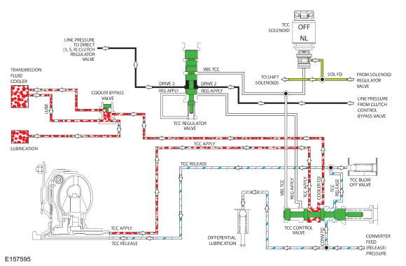
Pressure for TCC release is supplied by the main pressure regulator valve to the TCC control valve through the CONV FD circuit. The CONV FD circuit also supplies lubrication for the differential. When the TCC is released, the TCC control valve is positioned by the TCC solenoid to direct CONV FD pressure to the TCC RELEASE circuit to release the TCC. TCC RELEASE pressure returns to the TCC control valve through the TCC APPLY circuit. The position of the TCC control valve opens the TCC APPLY circuit to the COOLER FD circuit which allows the transmission fluid returned from the torque converter to cycle through the thermal bypass valve circuit when the TFT is below 80°C-93°C (176°F-200°F) or the transmission fluid cooler when the temperature is above 80°C-93°C (176°F-200°F).
Return transmission fluid from the thermal bypass valve or the transmission fluid cooler supplies transmission lubrication through the LUBE circuit which runs through the input shaft.
For lubrication passage location and description, refer to Hydraulic Circuit Identification Chart.
The position of the TCC control valve is controlled by pressure from the TCC solenoid through the VBS TCC circuit. The TCC solenoid is controlled by the PCM.
Torque Converter Clutch (TCC) and Lubrication Circuits TCC Applied
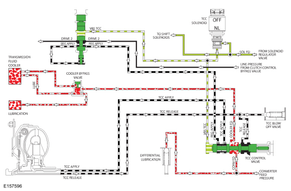
When the TCC clutch is applied, the TCC solenoid applies pressure to the TCC control and regulator valves to position the valves to apply the TCC clutch. Regulated line pressure is supplied to the TCC control valve through the REG APPLY circuit by the TCC regulator valve. The TCC control valve directs the regulated line pressure from the REG APPLY circuit to the TCC APPLY circuit to apply the TCC. The TCC control valve blocks the TCC RELEASE circuit to maintain pressure in the TCC APPLY circuit. The TCC control valve directs the CONV FD circuit to the COOLER FD circuit to allow the transmission fluid to flow through the thermal bypass valve or the transmission fluid cooler to the LUBE circuit to lubricate the transmission.
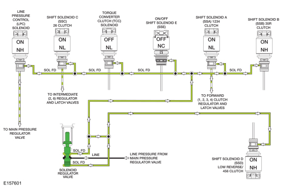
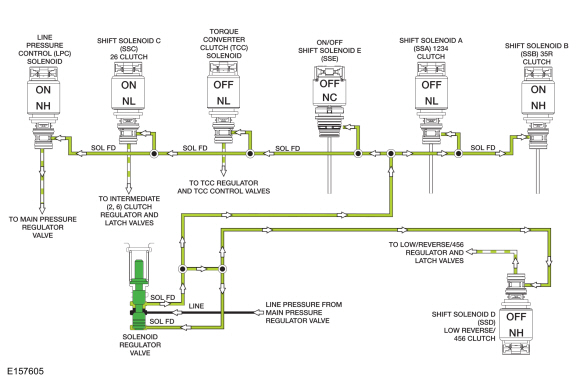
PARK and NEUTRAL Position Solenoid Hydraulic Circuits
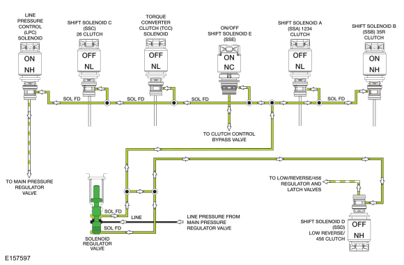
Line pressure from the main pressure regulator valve is directed to the individual shift, TCC and LPC solenoids by the solenoid regulator valve through the SOL FD circuit. The solenoids, controlled by the PCM, direct the fluid to the valves that they control.
The LPC solenoid applies varying pressure to the main pressure regulator valve to control line pressure.
In the PARK and NEUTRAL positions, SSD applies varying pressure to the low reverse/456 regulator and latch valves through the VBS CBR1/456 hydraulic circuit to position the valves to apply the low/reverse clutch. ON/OFF SSE directs pressure to the clutch control bypass valve to position the valve to direct regulated line pressure from the low reverse/456 regulator valve to the low/reverse clutch.
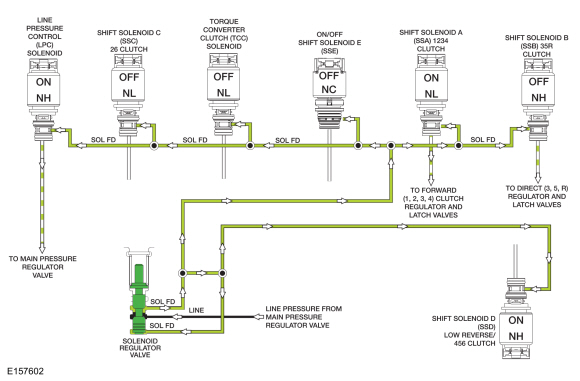
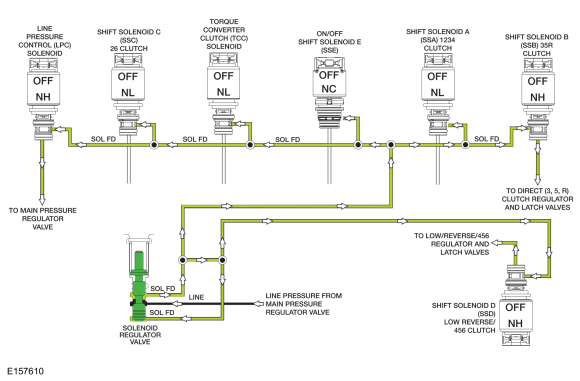
REVERSE Position Solenoid Hydraulic Circuits
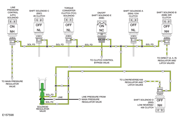
In the REVERSE position, SSD applies varying pressure to the low reverse/456 regulator and latch valves through the VBS CBR1/456 hydraulic circuit to position the valves to apply the low/reverse clutch. ON/OFF SSE directs pressure to the clutch control bypass valve to position the valve to direct regulated line pressure from the low reverse/456 regulator valve to the low/reverse clutch. The clutch control bypass valve also directs line pressure from the REVERSE circuit to the 35R regulator valve through the C35R FD and DRIVE 2/C35R FD circuits. SSB directs varying pressure to the 35R regulator and latch valves through the VBS C35R hydraulic circuit to apply the direct (3, 5, R) clutch.
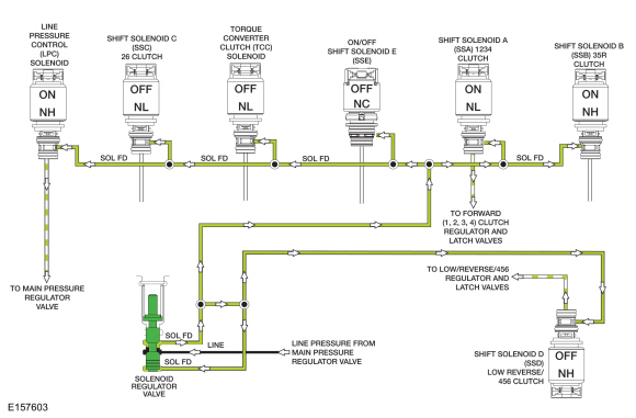
Manual Low Position and 1st Gear Below 8 km/h (5 mph) Solenoid Hydraulic Circuits
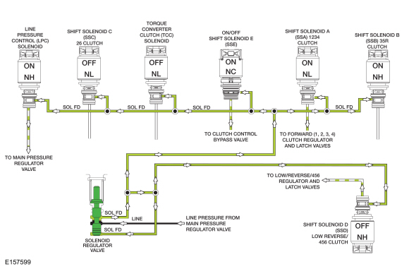
1st Gear Above 8 km/h (5 mph) Solenoid Hydraulic Circuits
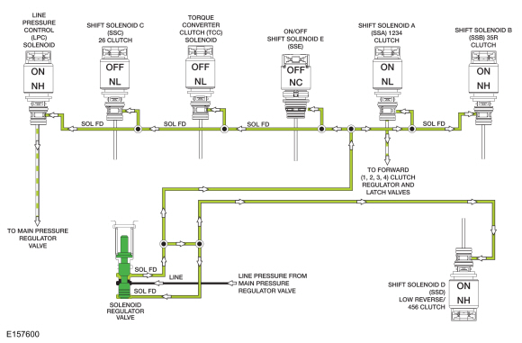
In 1st gear, SSA applies varying pressure to the 1234 clutch regulator and latch valves through the VBS C1234 hydraulic circuit to apply the forward (1, 2, 3, 4) clutch.
When vehicle speed is below 8 km/h (5 mph), or the selector lever is in the manual low position, SSD applies varying pressure to the low reverse/456 regulator and latch valves through the VBS CBR1/456 hydraulic circuit to position the valves to apply the low/reverse clutch. ON/OFF SSE directs pressure to the clutch control bypass valve to position the valve to direct regulated line pressure from the low reverse/456 regulator valve to the low/reverse clutch. As vehicle speed increases above 8 km/h (5 mph) in 1st gear, SSD removes pressure from the low reverse/456 regulator and latch valves and SSE removes pressure from the clutch control bypass valve to release the low/reverse clutch.
2nd Gear Solenoid Hydraulic Circuits
In 2nd gear, the forward (1, 2, 3, 4) clutch remains applied. SSC applies varying pressure to the 26 regulator and latch valves through the VBS CB26 hydraulic circuit to apply the intermediate (2, 6) clutch.
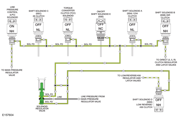
3rd Gear Solenoid Hydraulic Circuits
In 3rd gear, the forward (1, 2, 3, 4) clutch remains applied. SSC releases pressure to the 26 regulator and latch valves to release the intermediate (2, 6) clutch. SSB directs pressure to the 35R regulator and latch valves through the VBS CB26 hydraulic circuit to apply the direct (3, 5, R) clutch.
4th Gear Solenoid Hydraulic Circuits
In 4th gear, the forward (1, 2, 3, 4) clutch remains applied. SSB releases pressure to the 35R regulator and latch valves. SSD directs pressure to the low reverse/456 regulator and latch valves through the VBS CBR1/456 hydraulic circuit. With SSE released, the clutch control bypass valve directs the regulated line pressure from the low reverse/456 regulator valve to the overdrive (4, 5, 6) clutch to apply the clutch.
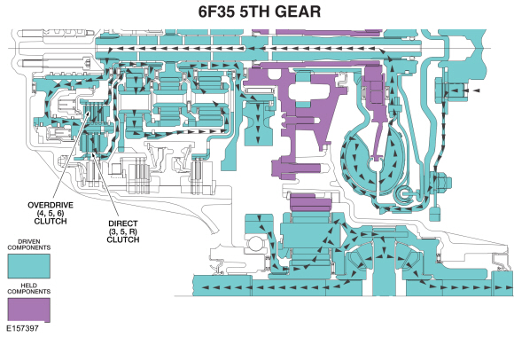
5th Gear Solenoid Hydraulic Circuits
In 5th gear, the overdrive (4, 5, 6) clutch remains applied. SSA releases pressure to the 1234 regulator and latch valves to release the forward (1, 2, 3, 4) clutch. SSB directs pressure to the 35R regulator and latch valves through the VBS C35R hydraulic circuit to apply the direct (3, 5, R) clutch.
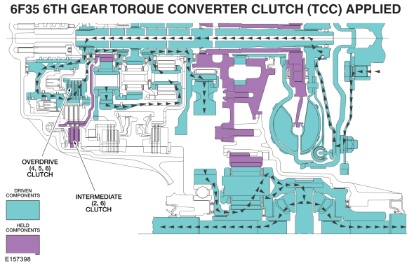
6th Gear Solenoid Hydraulic Circuits with the TCC applied
In 6th gear, the overdrive (4, 5, 6) clutch remains applied. SSB releases pressure to the 35R regulator and latch valves. SSC applies varying pressure to the 26 clutch regulator and latch valves through the VBS CB26 hydraulic circuit to apply the intermediate (2, 6) clutch.
The TCC can be applied in 4th, 5th or 6th gear. To apply the TCC, the TCC solenoid applies pressure to the TCC regulator valve and the TCC control valve to position the valves to apply the clutch.
5th Gear Failsafe Solenoid Hydraulic Circuits
During a mechanical, hydraulic or electrical failure with the manual lever in the DRIVE position, the transmission defaults to 5th gear. When the transmission is in 5th gear failsafe, the PCM does not control the shift solenoids and they default to their normal state (maximum pressure, minimum pressure, on or off). The LPC solenoid defaults to maximum pressure, SSA defaults to minimum pressure, SSB defaults to maximum pressure, SSC defaults to minimum pressure, SSD defaults to maximum pressure and the TCC solenoid defaults to minimum pressure.
With SSB applying maximum pressure to the direct (3, 5, R) regulator and latch valves, the direct (3, 5, R) clutch is applied. With SSD applying maximum pressure to the low reverse/456 regulator and latch valves with SSE in the OFF position, the overdrive (4, 5, 6) clutch is applied, providing 5th gear.
Solenoid Body
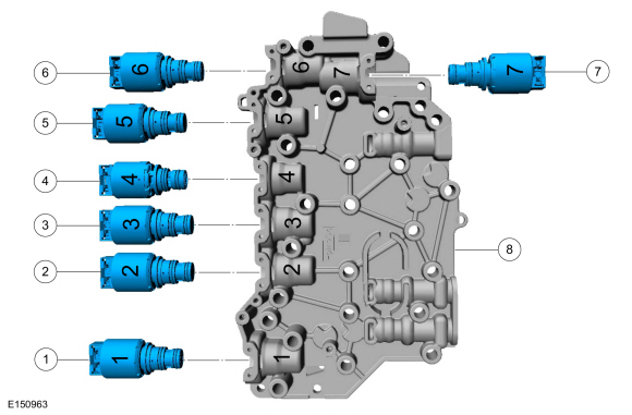
| Item | Description |
| 1 | LPC solenoid |
| 2 | SSC |
| 3 | TCC solenoid |
| 4 | SSE ON/OFF solenoid |
| 5 | SSA |
| 6 | SSB |
| 7 | SSD |
| 8 | Solenoid body |
Solenoid Body
The solenoid body contains 7 solenoids: 5 shift solenoids SSA, SSB, SSC, SSD and SSE, 1 TCC solenoid and 1 LPC solenoid. The TFT sensor is located in the solenoid body. The solenoid body is serviced as an assembly.
The solenoid body has a unique strategy data file that must be downloaded to the PCM. There is a 7-digit solenoid body identification and a 13-digit solenoid body strategy for each solenoid body. When a new solenoid body or transmission is installed, the scan tool must be used to get the solenoid body strategy data file and download it into the PCM.
If the PCM is replaced and the PCM data cannot be inhaled or exhaled, the solenoid body identification and solenoid body strategy must be downloaded into the PCM.
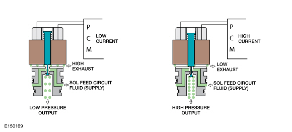
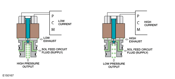
This transmission uses 3 types of solenoids: On/Off, normally low and normally high. On/Off solenoids open or close hydraulic passages based on the voltage signal it receives. Normally low solenoids provide hydraulic pressure proportional to supplied current. A normally low solenoid will not provide pressure without current, while it will supply high pressure with high current. Normally high solenoids provide pressure inversely proportional to supplied current. Normally high solenoids provide full output of pressure with no current and very low pressure with high current.
ON/OFF Solenoids
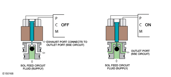
| Item | Description |
| SSE | Normally closed solenoid that blocks SOL FEED pressure from the SSE circuit. When energized, pressure from the SSE circuit positions the multiplex shift valve to direct CBLR/C456 SUPPLY pressure to the low reverse clutch. |
Normally Low Solenoids
| Item | Description |
| SSA | SSA blocks SOL FEED pressure from the SSA SIG circuit when low current is supplied. When energized, SSA SIG pressure positions the CB1234 clutch regulator and boost valves to direct CB1234 SUP pressure to apply the forward clutch. |
| SSC | SSC blocks SOL FEED pressure to the SSC SIG circuit when low current is supplied. When energized, SSC SIG pressure positions the CB26 clutch regulator valve to direct CB26FD/CB1234FD pressure to apply the intermediate clutch. |
| TCC solenoid | The TCC solenoid is used in the transmission control system to control the application, modulation and release of the torque converter clutch. The TCC solenoid blocks SOL FEED pressure to the TCC SOL SIG circuit when low current is supplied. When energized, TCC SOL SIG pressure positions the TCC reg apply and control valves to direct REG APPLY pressure to apply the torque converter. |
Normally High Solenoids
| Item | Description |
| SSB | SSB feeds SOL FEED pressure to the SSB SIG circuit to position the direct (3,5,R) clutch regulator and boost valves to apply the direct (3,5,R) clutch. When energized, SSB blocks SSB SIG to position the direct clutch (3,5,R) regulator and boost valves to release the direct (3,5,R) clutch. |
| SSD | SSD feeds SOL FEED pressure to the SSD SIG circuit to position the CBLR/C456 regulator and boost valves to apply either the low/reverse clutch or the overdrive (4,5,6) clutch. When energized, SSD blocks SSD SIG to position the CBLR/C456 regulator and boost valves to release either the low/reverse clutch or the overdrive (4,5,6) clutch. |
| LPC solenoid | The LPC solenoid is used to apply resistive force to the main regulator valve to adjust line pressure. Line pressure is inversely proportional to the current supplied to the LPC solenoid. As current decreases, line pressure increases. |
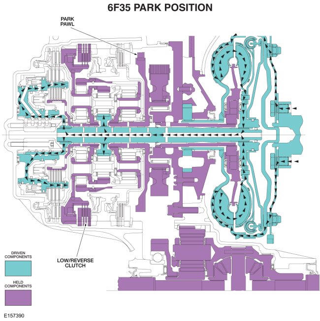
Park
Park Clutch Application Chart
| Gear | Forward (1,2,3,4) | Direct (3,5,R) | Intermediate (2,6) | Low / Reverse (L,R) | Overdrive (4,5,6) | Low-OWC |
| Park | H | |||||
| Planetary Components | Front sun | Rear sun | Rear sun | Rear carrier/center ring | Rear carrier/center ring | Rear carrier/center ring |
H = Holding
Park Position Solenoid Operation Chart
| Base Selector Lever Position | PCM Commanded Gear | SSA NL (1,2,3,4) | SSB NH (3,5,R) | SSC NL (2,6) | SSD NH (L,R,4,5,6) | SSE (On/ Off) NC | TCC NL |
| P | P | Off | On | Off | Off | On | Off |
NC = Normally Closed
NH = Normally High
NL = Normally Low
Powerflow
- With the selector lever in PARK, the low/reverse clutch holds the rear planetary carrier/center ring gear stationary.
- The park pawl holds the rear ring/front planetary carrier stationary.
- The turbine shaft drives the center sun gear.
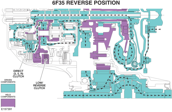
Reverse
Reverse Clutch Application Chart
| Gear | Forward (1,2,3,4) | Direct (3,5,R) | Intermediate (2,6) | Low / Reverse (L,R) | Overdrive (4,5,6) | Low-OWC |
| Reverse | D | H | ||||
| Planetary Components | Front sun | Rear sun | Rear sun | Rear carrier/center ring | Rear carrier/center ring | Rear carrier/center ring |
H = Holding
D = Driving
Reverse Position Solenoid Operation Chart
| Base Selector Lever Position | PCM Commanded Gear | SSA NL (1,2,3,4) | SSB NH (3,5,R) | SSC NL (2,6) | SSD NH (L,R,4,5,6) | SSE (On/ Off) NC | TCC NL |
| R | R | Off | Off | Off | Off | On | Off |
NC = Normally Closed
NH = Normally High
NL = Normally Low
Powerflow
- With the selector lever in REVERSE, the low/reverse clutch holds the rear planetary carrier/center ring gear stationary.
- The direct clutch drives the rear sun gear.
- The rear ring/front planetary carrier transfers torque to the output hub in a reverse direction with a ratio of 2.88.
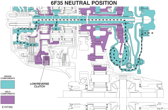
Neutral
Neutral Clutch Application Chart
| Gear | Forward (1,2,3,4) | Direct (3,5,R) | Intermediate (2,6) | Low / Reverse (L,R) | Overdrive (4,5,6) | Low-OWC |
| Neutral | H | |||||
| Planetary Components | Front sun | Rear sun | Rear sun | Rear carrier/center ring | Rear carrier/center ring | Rear carrier/center ring |
H = Holding
Neutral Position Solenoid Operation Chart
| Base Selector Lever Position | PCM Commanded Gear | SSA NL (1,2,3,4) | SSB NH (3,5,R) | SSC NL (2,6) | SSD NH (L,R,4,5,6) | SSE (On/ Off) NC | TCC NL |
| N | N | Off | On | Off | Off | On | Off |
NC = Normally Closed
NH = Normally High
NL = Normally Low
Powerflow
- With the selector lever in NEUTRAL, the low/reverse clutch holds the rear planetary carrier/center ring gear stationary.
- The turbine shaft drives the center sun gear.
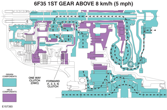
1st Gear
NOTE: The transmission operates differently in 1st gear above and below 8 km/h (5 mph). Transmission operation is the same below 8 km/h (5 mph) and in the LOW position.
1st Gear Above 8 km/h (5 mph) Clutch Application Chart
| Gear | Forward (1,2,3,4) | Direct (3,5,R) | Intermediate (2,6) | Low / Reverse (L,R) | Overdrive (4,5,6) | Low-OWC |
| 1st Gear D | H | H | ||||
| Planetary Components | Front sun | Rear sun | Rear sun | Rear carrier/center ring | Rear carrier/center ring | Rear carrier/center ring |
H = Holding
1st Gear LOW Position and Below 8 km/h (5 mph) Clutch Application Chart
| Gear | Forward (1,2,3,4) | Direct (3,5,R) | Intermediate (2,6) | Low / Reverse (L,R) | Overdrive (4,5,6) | Low-OWC |
| 1st Gear D | H | H | H | |||
| Planetary Components | Front sun | Rear sun | Rear sun | Rear carrier/center ring | Rear carrier/center ring | Rear carrier/center ring |
H = Holding
1st Gear Above 8 km/h (5 mph) Solenoid Operation Chart
| Base Selector Lever Position | PCM Commanded Gear | SSA NL (1,2,3,4) | SSB NH (3,5,R) | SSC NL (2,6) | SSD NH (L,R,4,5,6) | SSE (On/ Off) NC | TCC NL |
| D | 1 | On | On | Off | On | Off | Off |
NC = Normally Closed
NH = Normally High
NL = Normally Low
1st Gear LOW Position and Below 8 km/h (5 mph) Solenoid Operation Chart
| Base Selector Lever Position | PCM Commanded Gear | SSA NL (1,2,3,4) | SSB NH (3,5,R) | SSC NL (2,6) | SSD NH (L,R,4,5,6) | SSE (On/ Off) NC | TCC NL |
| L | 1 | On | On | Off | Off | On | Off |
NC = Normally Closed
NH = Normally High
NL = Normally Low
Powerflow
- In first gear, the forward clutch holds the front sun gear stationary.
- The rear planetary carrier/center ring gear is held stationary by the low One-Way Clutch (OWC) and/or the low reverse (1, R) clutch.
- The turbine shaft transfers torque to the center sun gear. The center sun gear transfers the torque to the center planetary carrier/front ring gear. The front ring gear transfers torque to the front planetary carrier/rear ring gear and the output hub to produce a ratio of 4.48.
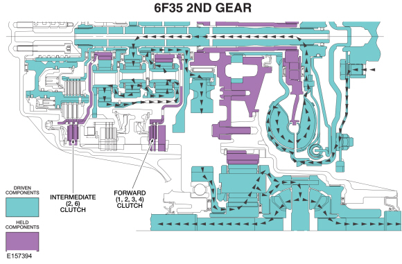
2nd Gear
2nd Gear Clutch Application Chart
| Gear | Forward (1,2,3,4) | Direct (3,5,R) | Intermediate (2,6) | Low / Reverse (L,R) | Overdrive (4,5,6) | Low-OWC |
| 2nd Gear D | H | H | ||||
| Planetary Components | Front sun | Rear sun | Rear sun | Rear carrier/center ring | Rear carrier/center ring | Rear carrier/center ring |
H = Holding
2nd Gear Solenoid Operation Chart
| Base Selector Lever Position | PCM Commanded Gear | SSA NL (1,2,3,4) | SSB NH (3,5,R) | SSC NL (2,6) | SSD NH (L,R,4,5,6) | SSE (On/ Off) NC | TCC NL |
| D | 2 | On | On | On | On | Off | Off |
NC = Normally Closed
NH = Normally High
NL = Normally Low
Powerflow
- In second gear the forward clutch holds the front sun gear stationary.
- The intermediate clutch holds the rear sun gear stationary.
- The turbine shaft transfers torque to the center sun gear. The center sun gear transfers torque to the center ring gear/rear planetary carrier.
- The rear planetary carrier transfers the torque to the rear ring gear/front planetary carrier and the output hub to produce a gear ratio of 2.87.
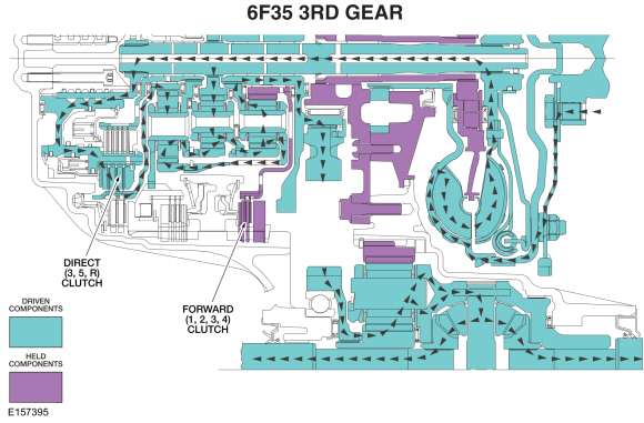
3rd Gear
3rd Gear Clutch Application Chart
| Gear | Forward (1,2,3,4) | Direct (3,5,R) | Intermediate (2,6) | Low / Reverse (L,R) | Overdrive (4,5,6) | Low-OWC |
| 3rd Gear D | H | D | ||||
| Planetary Components | Front sun | Rear sun | Rear sun | Rear carrier/center ring | Rear carrier/center ring | Rear carrier/center ring |
H = Holding
D = Driving
3rd Gear Solenoid Operation Chart
| Base Selector Lever Position | PCM Commanded Gear | SSA NL (1,2,3,4) | SSB NH (3,5,R) | SSC NL (2,6) | SSD NH (L,R,4,5,6) | SSE (On/ Off) NC | TCC NL |
| D | 3 | On | Off | Off | On | Off | Off |
NC = Normally Closed
NH = Normally High
NL = Normally Low
Powerflow
- In third gear the forward clutch holds the front sun gear stationary.
- The direct clutch drives the rear sun gear.
- Power flows from the center sun gear to the center planetary carrier/front ring gear. From there, torque is transferred to the rear ring gear/front planetary carrier.
- Power also flows from the rear sun gear to the rear ring gear/front planetary carrier.
- The two inputs to the front planetary carrier combine and transfer torque to the output hub to produce a gear ratio of 1.84.
4th Gear
4th Gear Clutch Application Chart
| Gear | Forward (1,2,3,4) | Direct (3,5,R) | Intermediate (2,6) | Low / Reverse (L,R) | Overdrive (4,5,6) | Low-OWC |
| 4th Gear D | H | D | ||||
| Planetary Components | Front sun | Rear sun | Rear sun | Rear carrier/center ring | Rear carrier/center ring | Rear carrier/center ring |
H = Holding
D = Driving
4th Gear Solenoid Operation Chart
| Base Selector Lever Position | PCM Commanded Gear | SSA NL (1,2,3,4) | SSB NH (3,5,R) | SSC NL (2,6) | SSD NH (L,R,4,5,6) | SSE (On/ Off) NC | TCC NL |
| D | 4 | On | On | Off | Off | Off | On/Off |
NC = Normally Closed
NH = Normally High
NL = Normally Low
Powerflow
- In fourth gear the forward clutch holds the front sun gear stationary.
- The overdrive clutch drives the rear planetary carrier/center ring gear.
- Power flows from turbine shaft to the center sun gear and center ring gear.
- The two inputs to the center planetary carrier combine and transfer torque to the front ring gear.
- The front ring gear transfers the torque to the front planetary carrier and onto the output hub to produce a gear ratio of 1.41.

5th Gear
5th Gear Clutch Application Chart
| Gear | Forward (1,2,3,4) | Direct (3,5,R) | Intermediate (2,6) | Low / Reverse (L,R) | Overdrive (4,5,6) | Low-OWC |
| 5th Gear D | D | D | ||||
| Planetary Components | Front sun | Rear sun | Rear sun | Rear carrier/center ring | Rear carrier/center ring | Rear carrier/center ring |
D = Driving
5th Gear Solenoid Operation Chart
| Base Selector Lever Position | PCM Commanded Gear | SSA NL (1,2,3,4) | SSB NH (3,5,R) | SSC NL (2,6) | SSD NH (L,R,4,5,6) | SSE (On/ Off) NC | TCC NL |
| D | 5 | Off | Off | Off | Off | Off | On/Off |
NC = Normally Closed
NH = Normally High
NL = Normally Low
Powerflow
- In fifth gear the overdrive clutch drives the rear planetary carrier/center ring gear.
- The direct clutch drives the rear sun gear.
- The turbine shaft transfers torque to the center sun gear, rear sun gear, and rear planetary carrier/center ring gear.
- The torque from the three inputs locks the three planetary gearsets which produces a gear ratio of 1 to 1.
Fail-safe Mode
- Because both SSD and SSB apply the clutches they control when they are turned OFF, 5th gear is the fail-safe.
6th Gear
6th Gear Clutch Application Chart
| Gear | Forward (1,2,3,4) | Direct (3,5,R) | Intermediate (2,6) | Low / Reverse (L,R) | Overdrive (4,5,6) | Low-OWC |
| 6th Gear D | H | D | ||||
| Planetary Components | Front sun | Rear sun | Rear sun | Rear carrier/center ring | Rear carrier/center ring | Rear carrier/center ring |
H = Holding
D = Driving
6th Gear Solenoid Operation Chart
| Base Selector Lever Position | PCM Commanded Gear | SSA NL (1,2,3,4) | SSB NH (3,5,R) | SSC NL (2,6) | SSD NH (L,R,4,5,6) | SSE (On/ Off) NC | TCC NL |
| D | 6 | Off | On | On | Off | Off | On/Off |
NC = Normally Closed
NH = Normally High
NL = Normally Low
Powerflow
- In sixth gear the overdrive clutch drives the rear planetary carrier/center ring gear.
- The intermediate clutch holds the rear sun gear.
- The torque from the rear planetary carrier is transferred to the rear ring gear/front planetary carrier and the output hub which produces a gear ratio of 0.74.
 Transmission Description. Description and Operation
Disassembled Views
Auto-Start-Stop
Item
Part Number
Description
1
70057005
Transmission case
2
7A1307A130
Clutch support tower
3
7D0197D019
Clutch support tower seals (4 required)
4
W302855W302855
Clutch support tower bolt (3 required)
5
7F2427F242
No...
 Forward Clutch Assembly. Description and Operation
Forward (1, 2, 3, 4) Clutch Exploded View
Item
Description
1
Transmission case
2
Center support
3
Forward (1, 2, 3, 4) clutch piston
4
Forward (1, 2, 3, 4) clutch piston return spring
5
Forward (1, 2, 3, 4) clutch piston snap ring retainer
6
Forward (1, 2, 3, 4) clutch pis..
Other information:
Ford Fusion 2013–2020 Service Manual: Active Torque Coupling Configuration. General Procedures
Configuration NOTICE: If the ATC (Active Torque Coupling) solenoid bar code information is not correct, Rear Drive Unit (RDU) damage or driveability concerns can occur. Using a diagnostic scan tool, under the toolbox icon select Powertrain then select Automatic Traction Control Barcode Entry. Follow the instructions displayed on the diagnostic scan tool. Enter the 4-d..
Ford Fusion 2013–2020 Service Manual: Power Transfer Unit Draining and Filling. General Procedures
Materials Name Specification Motorcraft® SAE 75W-140 Synthetic Rear Axle LubricantXY-75W140-QL WSL-M2C192-A Draining With the vehicle in NEUTRAL, position it on hoist. Refer to: Jacking and Lifting - Overview (100-02 Jacking and Lifting, Description and Operation). If equipped. Remove the retainers and the underbody shield. ..
Categories
- Manuals Home
- 2nd Generation Ford Fusion Owners Manual
- 2nd Generation Ford Fusion Service Manual
- Automatic Transmission - 6-Speed Automatic Transmission – 6F35
- Transmission - 1.5L EcoBoost (118kW/160PS) – I4. Removal and Installation
- Engine - 1.5L EcoBoost (118kW/160PS) – I4
- New on site
- Most important about car
Fuel Quality
Choosing the Right Fuel
Your vehicle is designed to operate on regular unleaded gasoline with a minimum pump (R+M)/2 octane rating of 87.