Ford Fusion: Side Panel Sheet Metal Repairs / Side Panel. Removal and Installation
Special Tool(s) / General Equipment
| Resistance Spotwelding Equipment | |
| Spherical Cutter | |
| Hot Air Gun | |
| Air Body Saw | |
| 8 mm Drill Bit | |
| MIG/MAG Welding Equipment | |
| Spot Weld Drill Bit | |
| Locking Pliers |
Materials
| Name | Specification |
|---|---|
| Metal Bonding Adhesive TA-1, TA-1-B, 3M™ 08115, LORD Fusor® 108B |
- |
| Seam Sealer TA-2-B, 3M™ 08308, LORD Fusor® 803DTM |
- |
| Flexible Foam Repair 3M™ 08463, LORD Fusor® 121 |
- |
Removal
NOTICE: Battery electric vehicle (BEV), hybrid electric vehicle (HEV) and plug-in hybrid electric vehicle (PHEV) contain a high-voltage battery. Before cutting or welding near the high-voltage battery it must be removed to avoid damage.
NOTICE: Sectioning may not take place within 50 mm of any restraints, hinges or door striker mounting points. Failure to meet this guideline may result in compromising structural integrity.
NOTE: The body side may be sectioned providing the above sectioning guideline is adhered. The following procedure assumes full component replacement. Adjust to meet repair needs.
NOTE: It is highly recommended the replacement panel be present before making any sectioning cuts on the vehicle.
NOTE: Left hand (LH) side shown, right hand (RH) side similar.
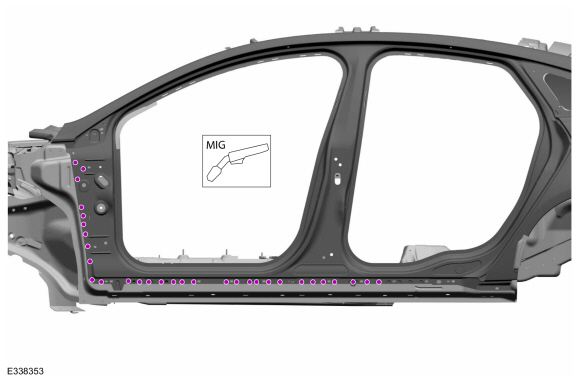
NOTE: Factory welds may be substituted with resistance or metal inert gas (MIG) plug welds. Resistance welds may not be placed directly over original location. They must be placed adjacent to original location and match factory welds in quantity. Metal inert gas (MIG) plug welds must equal factory welds in both location and quantity.
NOTE: Adequately protect all adjacent areas against cutting, grinding and welding procedures.
-
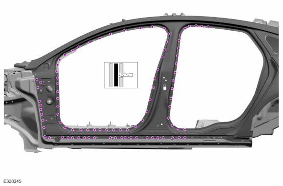
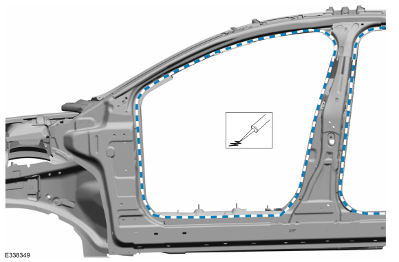
Possible sectioning points.
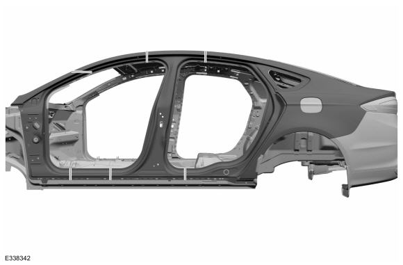 |
-
Depower the SRS.
Refer to: Supplemental Restraint System (SRS) Depowering and Repowering (501-20B) .
-
If Required:
Dimensionally restore the vehicle to pre-damage condition.
Refer to: Body and Frame (501-26) .
-
Remove the hood.
-
Remove the fender, splash shield and cowl panel grille.
Refer to: Fender (501-02) .
Refer to: Fender Splash Shield (501-02) .
Refer to: Cowl Panel Grille (501-02) .
-
Remove the front and rear door.
Refer to: Front Door (501-03 Body Closures, Removal and Installation).
Refer to: Rear Door (501-03 Body Closures, Removal and Installation).
-
Remove the roof.
Refer to: Roof Panel (501-28 Roof Sheet Metal Repairs, Removal and Installation).
Refer to: Roof Panel - Vehicles With: Roof Opening Panel (501-28 Roof Sheet Metal Repairs, Removal and Installation).
-
Remove the front door hinges.
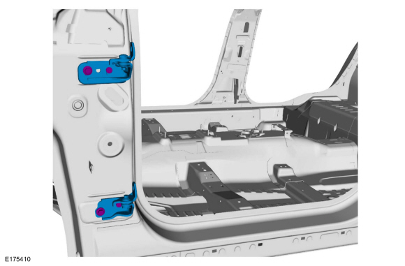 |
-
Remove the front door striker and rear door hinges.
 |
-
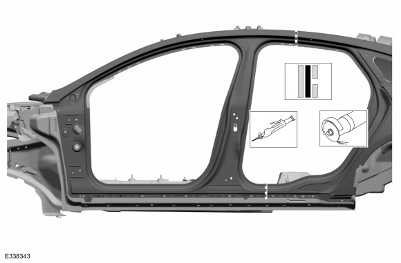
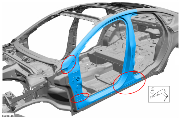
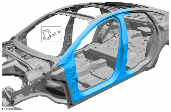
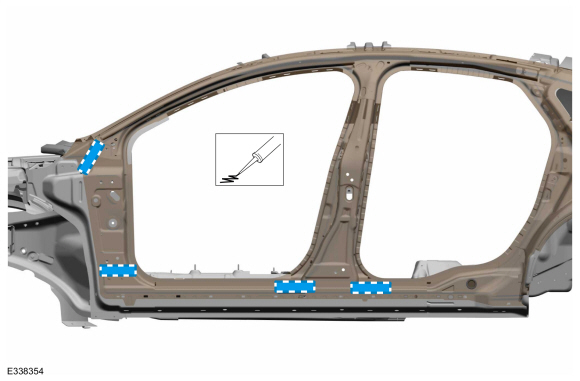
Carefully cut the outer panel only.
Use the General Equipment: Air Body Saw
Use the General Equipment: Spherical Cutter
 |
-
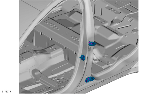
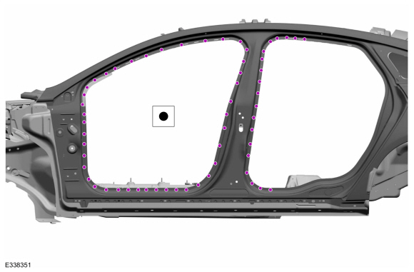
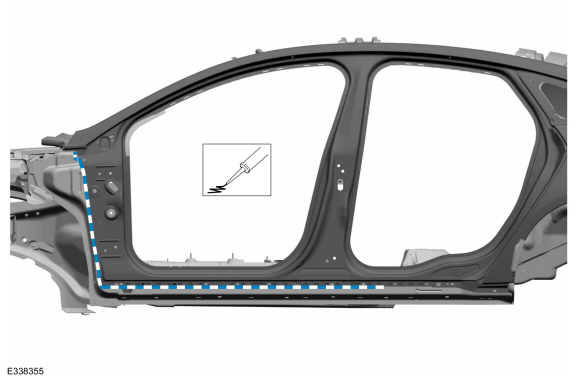
Remove the welds.
Use the General Equipment: Spot Weld Drill Bit
 |
-
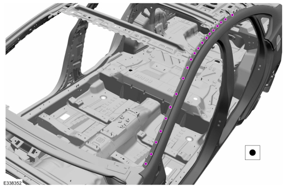
Remove the welds.
Use the General Equipment: Spot Weld Drill Bit
 |
-
NOTE: Pay particular attention to adhesive, sealer and noise, vibration and harshness (NVH) materials to aid in installation.
Remove the body side section.
Use the General Equipment: Hot Air Gun
 |
Installation
NOTICE: Battery electric vehicle (BEV), hybrid electric vehicle (HEV) and plug-in hybrid electric vehicle (PHEV) contain a high-voltage battery. Before cutting or welding near the high-voltage battery it must be removed to avoid damage.
NOTICE: The high-voltage battery in a battery electric vehicle (BEV), hybrid electric vehicle (HEV) or plug-in hybrid electric vehicle (PHEV) can be affected and damaged by excessively high temperatures. The temperature in some body shop paint booths can exceed 60° C (140° F). Therefore, during refinishing operations, the paint booth temperature must set at or below 60° C (140° F) with a bake time of 45 minutes or less. Temperatures in excess of 60° C (140° F) or bake durations longer than 45 minutes will require the high-voltage battery be removed from the vehicle prior to placing in the paint booth.
NOTICE: If refinishing cure temperatures exceed 60° C (140° F), the charge port light ring on plug-in vehicles must be removed.
NOTE: Left hand (LH) side shown, right hand (RH) side similar.
NOTE: Factory welds may be substituted with resistance or metal inert gas (MIG) plug welds. Resistance welds may not be placed directly over original location. They must be placed adjacent to original location and match factory welds in quantity. Metal inert gas (MIG) plug welds must equal factory welds in both location and quantity.
NOTE: Adequately protect all adjacent areas against cutting, grinding and welding procedures.
-
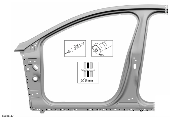
Carefully cut the replacement body side to fit the repair area and drill plug weld holes.
Use the General Equipment: Air Body Saw
Use the General Equipment: Spherical Cutter
Use the General Equipment: 8 mm Drill Bit
 |
-
Apply adhesive.
Material: Metal Bonding Adhesive / TA-1, TA-1-B, 3M™ 08115, LORD Fusor® 108B
 |
-
Apply adhesive.
Material: Metal Bonding Adhesive / TA-1, TA-1-B, 3M™ 08115, LORD Fusor® 108B
 |
-
Install, properly position and clamp the replacement body side.
Use the General Equipment: Locking Pliers
 |
-
Install the welds.
Use the General Equipment: Resistance Spotwelding Equipment
 |
-
Install the welds.
Use the General Equipment: Resistance Spotwelding Equipment
 |
-
Install the welds.
Use the General Equipment: MIG/MAG Welding Equipment
 |
-
Dress all welds as required using typical metal finishing techniques and materials.
-
Apply NVH material in areas noted during removal.
Material: Flexible Foam Repair / 3M™ 08463, LORD Fusor® 121
 |
-
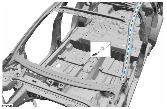
Seam Sealing:
All seams must be sealed to production level.
Material: Seam Sealer / TA-2-B, 3M™ 08308, LORD Fusor® 803DTM
 |
-
Install the roof.
Refer to: Roof Panel (501-28 Roof Sheet Metal Repairs, Removal and Installation).
Refer to: Roof Panel - Vehicles With: Roof Opening Panel (501-28 Roof Sheet Metal Repairs, Removal and Installation).
-
Refinish the entire repair using a Ford approved paint system.
-
Restore corrosion protection.
Refer to: Corrosion Prevention (501-25 Body Repairs - General Information, General Procedures).
-
Install the front door hinges.
Torque: 22 lb.ft (30 Nm)
 |
-
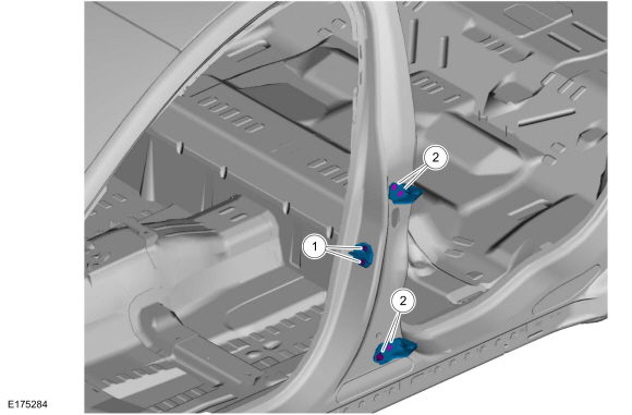
Install the front door striker and rear door hinges.
Torque:
1: 35 lb.ft (48 Nm)
2: 22 lb.ft (30 Nm)
 |
-
Install the front fender, splash shield and the cowl panel grille.
Refer to: Cowl Panel Grille (501-02) .
Refer to: Fender (501-02) .
Refer to: Fender Splash Shield (501-02) .
-
Install the hood.
-
Install and align the front and rear doors.
Refer to: Front Door (501-03 Body Closures, Removal and Installation).
Refer to: Rear Door (501-03 Body Closures, Removal and Installation).
Refer to: Rear Door Alignment (501-03 Body Closures, General Procedures).
Refer to: Front Door Alignment (501-03 Body Closures, General Procedures).
-
Repower the SRS.
Refer to: Supplemental Restraint System (SRS) Depowering and Repowering (501-20B) .

 Side Panel Extension. Removal and Installation
Special Tool(s) /
General Equipment
Resistance Spotwelding Equipment
Hot Air Gun
Knife
MIG/MAG Welding Equipment
Spot Weld Drill Bit
Locking Pliers
Materials
Name
Specification
Metal Bonding AdhesiveTA-1, TA-1-B, 3M™ 08115, LORD Fusor® 108B
-
Seam SealerTA-2-B, 3M™ 08308, LORD Fusor® 803DTM
-
Removal
NOTICE:
Battery ..
Other information:
Ford Fusion 2013–2020 Owners Manual: Engine Block Heater (IF EQUIPPED)
WARNING: Failure to follow engine block heater instructions could result in property damage or serious personal injury. WARNING: Do not use your heater with ungrounded electrical systems or two-pronged adapters. There is a risk of electrical shock. Note: The heater is most effective when outdoor temperatures are below 0°F (-18°C). The heater acts as a starting aid by warming the engine ..
Ford Fusion 2013–2020 Service Manual: Gateway Module A (GWM). Removal and Installation
Removal NOTE: Removal steps in this procedure may contain installation details. NOTE: If installing a new module, it is necessary to upload the module configuration information to the scan tool prior to removing the module. This information must be downloaded into the new module after installation. Upload the GWM configuration to the scan tool by following the scan tool on-scr..
Categories
- Manuals Home
- 2nd Generation Ford Fusion Owners Manual
- 2nd Generation Ford Fusion Service Manual
- Electrical
- Traction Control
- Memory Function
- New on site
- Most important about car
Fuel Quality
Choosing the Right Fuel
Your vehicle is designed to operate on regular unleaded gasoline with a minimum pump (R+M)/2 octane rating of 87.