Ford Fusion: Automatic Transmission - 6-Speed Automatic Transmission – 6F35 / Leakage Inspection. Diagnosis and Testing
Ford Fusion 2013–2020 Service Manual / Powertrain / Automatic Transmission / Automatic Transmission - 6-Speed Automatic Transmission – 6F35 / Leakage Inspection. Diagnosis and Testing
Leak Check Test
-
With the vehicle in NEUTRAL, position the vehicle on a hoist.
REFER to: Jacking and Lifting - Overview (100-02 Jacking and Lifting, Description and Operation).
-
Inspect the gasket and sealing areas for evidence of leakage.
-
Trace the transmission fluid leak to the highest point.
-
Clean area of suspected leak.
-
Lower vehicle.
-
Remove the transmission fluid fill plug.
-
Add leak detection dye to the transmission fluid. Use 1 fl oz
(30 ml) of dye solution for every 4 qt (3.8 L) of transmission fluid.
-
Road test the vehicle for at least 1 mile with at least 1 application of the TCC.
-
With the vehicle in NEUTRAL, position the vehicle on a hoist.
REFER to: Jacking and Lifting - Overview (100-02 Jacking and Lifting, Description and Operation).
-
If the source of the leak is obvious, repair as required.
-
After the repair, clean the affected area.
Leakage From Torque Converter Housing
Add leak detection dye 1 fl oz ( 30 ml) of dye solution for every 4 qt ( 3.8 L) of transmission fluid.
-
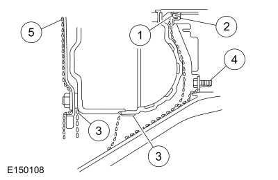
Leaks from the torque converter housing can originate from
several locations. The paths which the transmission fluid takes to reach
the bottom of the torque converter housing is shown in the
illustration. The 5 following steps correspond with the numbers in the
illustration.
-
Transmission fluid leaking by the converter hub seal lip
will tend to move along the drive hub and onto the back of the torque
converter. Except in the case of a total seal failure, transmission
fluid leakage by the lip of the seal will be deposited on the inside of
the torque converter housing only, near the outside diameter of the
housing.
-
Transmission fluid leakage by the outside diameter of the
torque converter impeller hub seal and the case will follow the same
path that leaks by the inside diameter of the converter hub seal follow.
-
Transmission fluid leakage from the converter cover weld or
the converter-to-flexplate stud weld will appear at outside diameter of
torque converter on the back face of the flexplate and in the converter
housing only near the flexplate. If a converter-to-flexplate lug, lug
weld or converter cover weld leak is suspected, remove the converter and
pressure check.
-
Transmission fluid leakage from the bolts inside the
converter housing will flow down the back of the torque converter
housing. Leakage may be from loose or missing bolts.
-
Engine oil leaks from the rear main oil.
-
Transmission fluid leaking by the converter hub seal lip
will tend to move along the drive hub and onto the back of the torque
converter. Except in the case of a total seal failure, transmission
fluid leakage by the lip of the seal will be deposited on the inside of
the torque converter housing only, near the outside diameter of the
housing.
-
Remove the torque converter.
-
Using a black light, observe the torque converter housing.
Inspect for evidence of dye from the pump bolts, pump seal, and torque
converter hub seal. Repair as required.
-
If the source of the leak is not evident, continue with this procedure to leak test the torque converter.
-
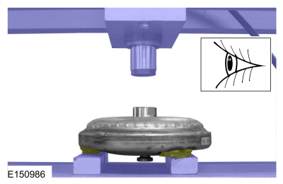
Place the torque converter in an arbor press. Support the torque converter on the mounting pads.
-
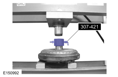
Install the torque converter leak tester (307-421) into the torque converter hub.
-
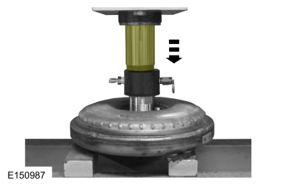
Secure the press. Apply enough force from the press to seal the
torque converter leak tester (307-421) into the torque converter hub.
-
Connect a compressed air supply to the torque converter leak tester (307-421).
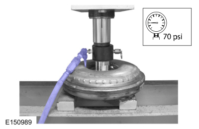
-
Inspect for leaks at the torque converter hub weld and seams
with air pressure applied to the valve. A soap bubble solution can be
applied around those areas to aid in the diagnosis. If any leaks are
present, install a new torque converter.
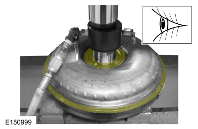
-
Inspect for leaks at the stud or mounting pad and balance weight
welds. A soap bubble solution can be applied around those areas to aid
in the diagnosis. If any leaks are present, install a new torque
converter.
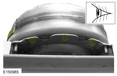
-
After leaks are repaired, clean the remaining transmission fluid dye from serviced areas.
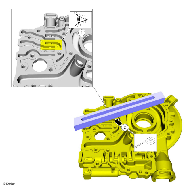
TCC Hydraulic Circuit Leak Paths
-
-
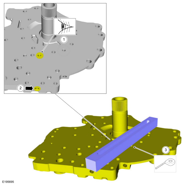
Inspect the aluminum pump housing near the TCC control valve for scoring or blockage.
-
Using a straight edge, inspect the aluminum pump housing near the TCC
control valve for evidence of any surface warping possibly causing
internal pressure leaks. Inspect the hydraulic passages for blockage.
-
Inspect the aluminum pump housing near the TCC control valve for scoring or blockage.
-
-
Inspect the stator support hydraulic passage for scoring or blockage.
-
Inspect the stator support cup plug and verify that it is installed correctly and not loose or missing.
-
Using a straight edge, inspect the stator support
hydraulic passage for evidence of any surface warping possibly causing
internal pressure leaks. Inspect the hydraulic passages for blockage.
-
Inspect the stator support hydraulic passage for scoring or blockage.
-
-
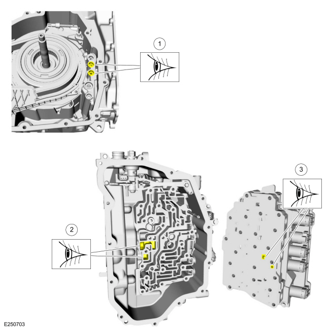
Inspect the pump to transmission case hydraulic passages and seals.
-
Inspect the transmission case to main control hydraulic passages.
-
Inspect the main control hydraulic passages.
-
Inspect the pump to transmission case hydraulic passages and seals.
-
-
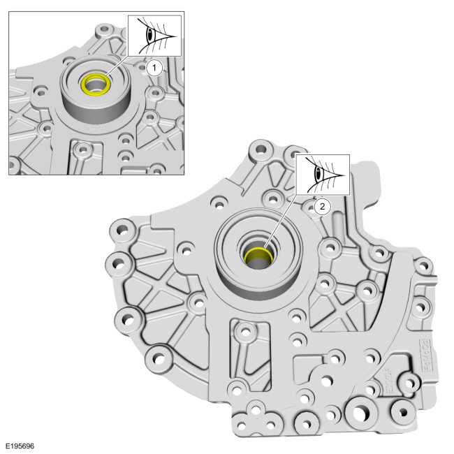
Inspect the turbine shaft oil seal on the stator support for wear or damage that would cause leaks.
-
Inspect the turbine shaft support bushing for wear or scoring that might cause pressure leaks.
-
Inspect the turbine shaft oil seal on the stator support for wear or damage that would cause leaks.
-
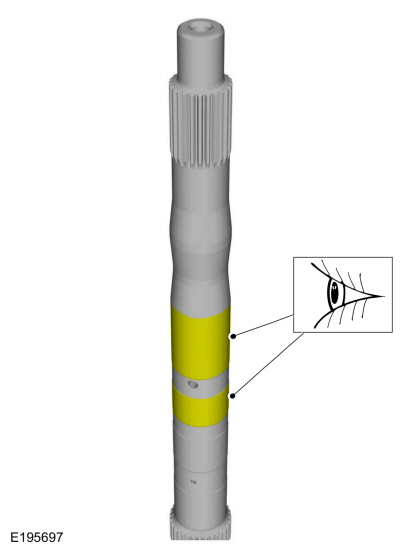
Inspect the turbine shaft seal and shaft support bushing
sealing surfaces on the turbine shaft for wear or scoring that might
cause pressure leaks.
 Diagnostic Strategy. Diagnosis and Testing
Overview
The
diagnostic process for each transmission concern will vary depending on
the symptoms and condition of the vehicle. The diagnostic process
below is an efficient method to collect as much data as possible about
the concern before performing a repair or removing the transmission from
the vehicle for teardown and further inspection...
 Parameter Identification (PID) Chart. Diagnosis and Testing
Diagnostic PID Chart
PID Acronym
PID Name
Description
APP1
APP sensor 1
APP
AST
Time Since Start
Time (in seconds) since the vehicle was started
CLRDIST
Distance since DTC cleared
Distance driven since PCM Diagnostic Trouble Codes (DTCs) were cleared
DTC PCM
Continuous Co..
Other information:
Ford Fusion 2013–2020 Owners Manual: Anti-Theft Alarm
The system will warn you of an unauthorized entry to your vehicle. It will be triggered if any door, the luggage compartment or the hood is opened without using the key, remote control or keyless entry keypad. The direction indicators will flash and the horn will sound if unauthorized entry is attempted while the alarm is armed. Take all remote controls to an authorized dealer if there is ..
Ford Fusion 2013–2020 Service Manual: Climate Control Housing - Vehicles With: Electronic Manual Temperature Control (EMTC). Removal and Installation
Removal NOTE: Removal steps in this procedure may contain installation details. Remove the instrument panel upper section. Refer to: Instrument Panel Upper Section (501-12 Instrument Panel and Console, Removal and Installation). Detach the wiring harness retainer, remove the nuts and the instrument panel upper brace. Torque: 133 lb.in (15 Nm) ..
Categories
- Manuals Home
- 2nd Generation Ford Fusion Owners Manual
- 2nd Generation Ford Fusion Service Manual
- Automatic Transmission Fluid Check - 1.5L EcoBoost™/2.0L EcoBoost™/2.5L. Automatic Transmission Fluid Check - 2.7L EcoBoost™
- Under Hood Overview - 1.5L EcoBoost™, 2.0L EcoBoost™, 2.5L, 2.7L EcoBoost™
- Main Control Valve Body. Removal and Installation
- New on site
- Most important about car
Manual Climate Control
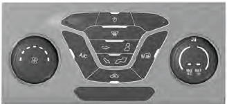
Note: Depending on your vehicle option package, the controls may look different from what you see here.
Copyright © 2026 www.fofusion2.com
