Ford Fusion: Climate Control System - General Information / Evaporator Inlet and Outlet Manifold - 2.7L EcoBoost (238kW/324PS). Removal and Installation
Special Tool(s) / General Equipment
| Hose Clamp Remover/Installer |
Removal
NOTICE: During the removal or installation of components, cap, tape or otherwise appropriately protect all openings and tubes/fittings to prevent the ingress of dirt or other contamination. Remove caps, tape and other protective materials prior to installation.
NOTE: Removal steps in this procedure may contain installation details.
-
Recover the refrigerant. Refer to the appropriate Recovery procedure in Group 412.
-
Drain the cooling system.
Refer to: Engine Cooling System Draining, Vacuum Filling and Bleeding (303-03D Engine Cooling - 2.7L EcoBoost (238kW/324PS), General Procedures).
-
With the vehicle in N, position it on a hoist.
Refer to: Jacking and Lifting - Overview (100-02 Jacking and Lifting, Description and Operation).
-
NOTICE: Make sure that all openings are sealed.
-
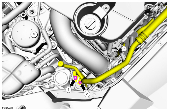
Remove the A/C compressor inlet line nut and disconnect the fitting. Discard the O-ring seal and gasket seal.
Torque: 159 lb.in (18 Nm)
-
Remove the condenser outlet line nut and disconnect the fitting. Discard the O-ring seal and gasket seal.
Torque: 80 lb.in (9 Nm)
-
Make sure to cover any open ports to prevent debris from entering the system.
-
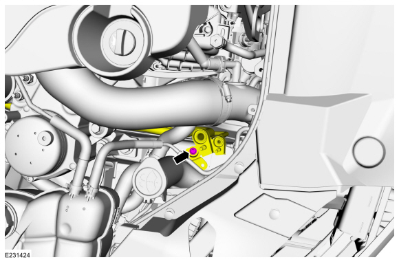
Remove the A/C compressor inlet line nut and disconnect the fitting. Discard the O-ring seal and gasket seal.
 |
-
Remove the evaporator inlet and outlet manifold bracket bolt.
Torque: 106 lb.in (12 Nm)
 |
-
Remove the RHF fender splash shield.
Refer to: Fender Splash Shield (501-02 Front End Body Panels, Removal and Installation).
-
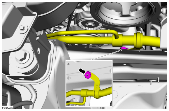
Remove the evaporator inlet and outlet manifold bracket nut.
Torque: 18 lb.in (2 Nm)
 |
-
Remove the air cleaner outlet pipe RH.
Refer to: Air Cleaner Outlet Pipe RH (303-12D Intake Air Distribution and Filtering - 2.7L EcoBoost (238kW/324PS), Removal and Installation).
-
NOTICE: The turbocharger compressor vanes can be damaged by even the smallest particles. When removing any turbocharger or engine air intake system component, ensure that no debris enters the system. Failure to do so may result in damage to the turbocharger.
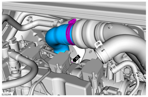
Loosen the clamps and remove the RH CAC intake upper pipe.
Torque: 44 lb.in (5 Nm)
 |
-
Remove the PCM.
Refer to: Powertrain Control Module (PCM) (303-14D Electronic Engine Controls - 2.7L EcoBoost (238kW/324PS), Removal and Installation).
-
-
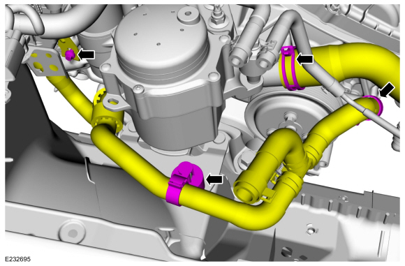
Release the clamp and disconnect the lower radiator hose.
Use the General Equipment: Hose Clamp Remover/Installer
-
Release the clamp and disconnect the heater hose.
Use the General Equipment: Hose Clamp Remover/Installer
-
Detach the heater hose retainer.
-
Remove the bolt and position the heater hose aside.
-
Release the clamp and disconnect the lower radiator hose.
 |
-
Remove the engine mount.
Refer to: Engine Mount (303-01D Engine - 2.7L EcoBoost (238kW/324PS), Removal and Installation).
-
-
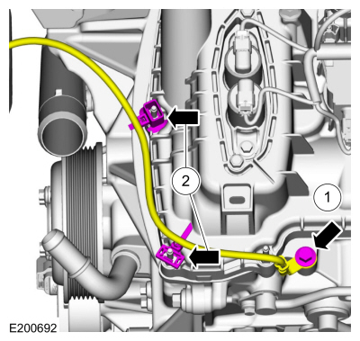
Remove the ground wire bolt.
Torque: 159 lb.in (18 Nm)
-
Detach the retainers and position the ground wire aside.
-
Remove the ground wire bolt.
 |
-
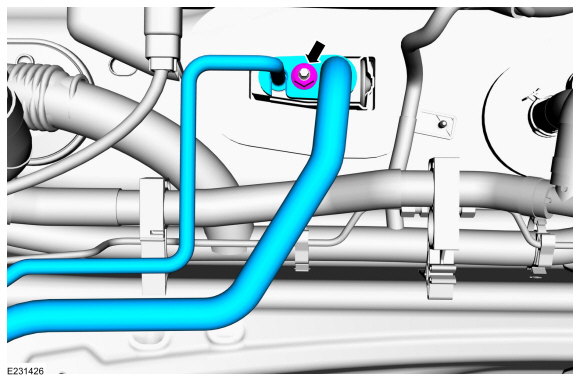
Remove the evaporator inlet and outlet manifold nut, disconnect the fitting and remove the evaporator inlet and outlet manifold. Discard the gasket seals.
-
Make sure to cover any open ports to prevent debris from entering the system.
Torque: 159 lb.in (18 Nm)
-
Make sure to cover any open ports to prevent debris from entering the system.
 |
Installation
-
To install, reverse the removal procedure.
-
NOTICE: Only use the specified material to lubricate the seals.
Install and lubricate new O-ring seals. Refer to the appropriate Specifications in Group 412.
-
Lubricate the refrigerant system with the correct amount
of clean PAG oil. Refer to the appropriate Refrigerant Oil Adding
procedure in Group 412.
-
Fill and bleed the cooling system.
Refer to: Engine Cooling System Draining, Vacuum Filling and Bleeding (303-03D Engine Cooling - 2.7L EcoBoost (238kW/324PS), General Procedures).
 Evaporator Inlet and Outlet Manifold. Removal and Installation
Removal
NOTICE:
During the removal or installation of components, cap, tape
or otherwise appropriately protect all openings and tubes/fittings to
prevent the ingress of dirt or other contamination...
 Evaporator Temperature Sensor. Removal and Installation
Removal
NOTE:
Removal steps in this procedure may contain installation details.
WARNING:
Before beginning any service procedure in this
section, refer to Safety Warnings in section 100-00 General Information...
Other information:
Ford Fusion 2013–2020 Owners Manual: Following a Vehicle. Following a Vehicle to a Complete Stop
Following a Vehicle WARNING: When following a vehicle that is braking, your vehicle does not always decelerate quickly enough to avoid a crash without driver intervention. Apply the brakes when necessary. Failure to follow this instruction could result in personal injury or death...
Ford Fusion 2013–2020 Service Manual: Rear Seat Backrest. Removal and Installation
Removal NOTE: Removal steps in this procedure may contain installation details. NOTE: The 40 percent backrest must be removed to allow removal of the 60 percent backrest. All backrests Remove the rear LH seatbelt buckle. Refer to: Rear Seatbelt Buckle LH (501-20A Seatbelt Systems, Removal and Installation)...
Categories
- Manuals Home
- 2nd Generation Ford Fusion Owners Manual
- 2nd Generation Ford Fusion Service Manual
- Traction Control
- Starter Motor. Removal and Installation
- Electrical
- New on site
- Most important about car
Power Door Locks
The power door lock control is on the driver and front passenger door panels.