Ford Fusion: Electronic Engine Controls - 1.5L EcoBoost (118kW/160PS) – I4 / Turbocharger Bypass Valve. Removal and Installation
Ford Fusion 2013–2020 Service Manual / Powertrain / Engine / Electronic Engine Controls - 1.5L EcoBoost (118kW/160PS) – I4 / Turbocharger Bypass Valve. Removal and Installation
Removal
NOTE: When removing any turbocharger air intake system components, make sure to cover any open ports to prevent debris from entering the system. The turbocharger compressor vanes can be damaged by even the smallest particles. All components need to be inspected and cleaned prior to installation or reassembly.
NOTE: Removal steps in this procedure may contain installation details.
-
-
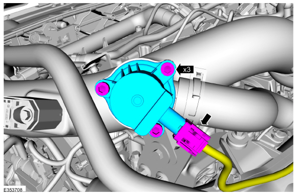
Disconnect the electrical connector.
-
Remove the bolts and the turbocharger bypass valve.
Torque: 53 lb.in (6 Nm)
-
Disconnect the electrical connector.
 |
Installation
-
To install, reverse the removal procedure.
 Powertrain Control Module (PCM). Removal and Installation
Special Tool(s) /
General Equipment
Ford Diagnostic Equipment
Removal
NOTE:
Removal steps in this procedure may contain installation details...
 Boost Pressure Sensor. Removal and Installation
Removal
NOTE:
Removal steps in this procedure may contain installation details.
Disconnect the electrical connector, remove the retainer and the turbocharger boost pressure sensor...
Other information:
Ford Fusion 2013–2020 Owners Manual: Engine Specifications - 1.5L EcoBoost™, 2.0L EcoBoost™, 2.5L, 2.7L EcoBoost™
Engine Specifications - 1.5L EcoBoost™ Drivebelt Routing Engine Specifications - 2.0L EcoBoost™ Drivebelt Routing Long drivebelt is on first pulley groove closest to engine Short drivebelt is on second pulley groove farthest from engine Engine Specifications - 2...
Ford Fusion 2013–2020 Service Manual: Audio Front Control Module (ACM). Removal and Installation
Removal NOTE: Make sure that any media is ejected from unit. NOTE: Removal steps in this procedure may contain installation details. WARNING: Before beginning any service procedure in this section, refer to Safety Warnings in section 100-00 General Information...
Categories
- Manuals Home
- 2nd Generation Ford Fusion Owners Manual
- 2nd Generation Ford Fusion Service Manual
- Traction Control
- Pre-Collision Assist (IF EQUIPPED)
- Body Control Module (BCM). Removal and Installation
- New on site
- Most important about car
Cross Traffic Alert System Sensors
The sensors are behind the rear bumper on both sides of your vehicle.
Copyright © 2026 www.fofusion2.com