Ford Fusion: Supplemental Restraint System / Restraints Control Module (RCM). Removal and Installation
Ford Fusion 2013–2020 Service Manual / Body and Paint / Body and Paint / Supplemental Restraint System / Restraints Control Module (RCM). Removal and Installation
Removal
NOTE: Removal steps in this procedure may contain installation details.
-
When installing a new RCM,
Programmable Module Installation (PMI) is required. Refer to the
diagnostic scan tool instructions to carry out Programmable Module
Installation (PMI).
-
If a SRS fault is present, continue to Step 3. Otherwise, turn the ignition off and wait at least one minute and continue to Step 4. WARNING:
Turn the ignition OFF and wait one minute to deplete
the backup power supply. Ignition must remain OFF until repair is
complete. Failure to follow this instruction may result in serious
personal injury or death in the event of an accidental deployment.
-
Depower the SRS.
Refer to: Supplemental Restraint System (SRS) Depowering and Repowering (501-20B Supplemental Restraint System, General Procedures).
-
Remove the floor console.
Refer to: Floor Console (501-12 Instrument Panel and Console, Removal and Installation).
-
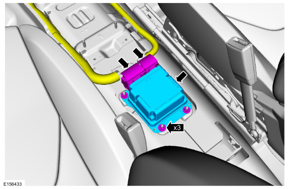
Disconnect the electrical connectors, remove the nuts and the RCM .
Torque: 80 lb.in (9 Nm)
 |
Installation
-
To install, reverse the removal procedure.
-
If the SRS was depowered, repower the SRS. Do not prove out the SRS at this time.
Refer to: Supplemental Restraint System (SRS) Depowering and Repowering (501-20B Supplemental Restraint System, General Procedures).
-
NOTE: This step is only necessary when installing a new component.
When installing a new RCM, Programmable Module Installation (PMI) is required. Refer to the diagnostic scan tool instructions to carry out Programmable Module Installation (PMI).
-
NOTE: This step is only necessary when installing a new component.
Using a diagnostic scan tool, carry out the ABS module initialization following the on-screen instruction.
-
-
If a new RCM was installed, prove out the SRS
as follows: Turn the ignition from ON to OFF. Wait 10 seconds, then
turn the ignition back to ON and monitor the airbag warning indicator
with the airbag modules installed. The airbag warning indicator
illuminates continuously for approximately 6 seconds and then turns off.
If a SRS fault is present, the airbag warning indicator either fails to light, remains lit continuously or flashes.
-
The flashing might not occur until approximately 30
seconds after the ignition has been turned from OFF to ON. This is the
time required for the RCM to complete the testing of the SRS. If the airbag warning indicator is inoperative and a SRS
fault exists, a chime sounds in a pattern of 5 sets of 5 beeps. If this
occurs, diagnose and repair the airbag warning indicator and any SRS faults.
-
If a new RCM was installed, prove out the SRS
as follows: Turn the ignition from ON to OFF. Wait 10 seconds, then
turn the ignition back to ON and monitor the airbag warning indicator
with the airbag modules installed. The airbag warning indicator
illuminates continuously for approximately 6 seconds and then turns off.
If a SRS fault is present, the airbag warning indicator either fails to light, remains lit continuously or flashes.
 Passenger Knee Airbag. Removal and Installation
Removal
NOTE:
Removal steps in this procedure may contain installation details.
WARNING:
Turn the ignition OFF and wait one minute to deplete
the backup power supply...
 Seat Position Sensor. Removal and Installation
Removal
NOTE:
Removal steps in this procedure may contain installation details.
NOTE:
RH seat shown, LH seat similar.
Remove the screw...
Other information:
Ford Fusion 2013–2020 Service Manual: Pinpoint Test - DTC: F. Diagnosis and Testing
B0011:11, B0011:12, B0011:13 and B0011:1A Refer to Wiring Diagrams Cell 46 for schematic and connector information. Normal Operation and Fault Conditions The RCM continuously monitors the passenger airbag stage 2 circuits for the following faults: Resistance out of range Unexpected voltage Short to ground Faulted passenger airbag If a fault is detected, t..
Ford Fusion 2013–2020 Owners Manual: Driver and Passenger Airbags
WARNING: Do not place your arms on the airbag cover or through the steering wheel. Failure to follow this instruction could result in personal injury. WARNING: Keep the areas in front of the airbags free from obstruction. Do not affix anything to or over the airbag covers. Objects could become projectiles during airbag deployment or in a sudden stop. Failure to follow this instruction cou..
Categories
- Manuals Home
- 2nd Generation Ford Fusion Owners Manual
- 2nd Generation Ford Fusion Service Manual
- Pre-Collision Assist (IF EQUIPPED)
- Front Controls Interface Module (FCIM). Removal and Installation
- Powertrain
- New on site
- Most important about car
Child Safety Locks
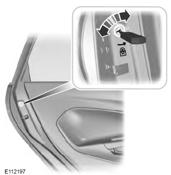
When these locks are set, the rear doors cannot be opened from the inside.

Copyright © 2026 www.fofusion2.com
